I2S Audio for ESP32~
This feature is not included in precompiled binaries
Add the following to the build environment and compile your build:
build_flags                 = ${env:tasmota32_base.build_flags}
                              -DUSE_I2S_ALL
lib_extra_dirs = lib/lib_audio added to the build environment The main difference to the older ESP8266 sound driver is the configuration of the various settings at runtime with the command i2sconfig, which uses a hidden driver file.
I2S (Inter-IC Sound) is a serial, synchronous communication protocol that is usually used for transmitting audio data between two digital audio devices.
The I2S framework of the ESP-IDF supports 3 communication modes which are standard, PDM and TDM. TDM is the most advanced mode and very uncommon in the IOT world - there is no support for it in Tasmota yet.
Support for different I2S modes varies across the ESP32 family:
| Target | Standard | PDM TX | PDM RX | TDM | ADC/DAC | LCD/Camera |
|---|---|---|---|---|---|---|
| ESP32 | I2S 0/1 | I2S 0 | I2S 0 | none | I2S 0 | I2S 0 |
| ESP32-S2 | I2S 0 | none | none | none | none | I2S 0 |
| ESP32-C3 | I2S 0 | I2S 0 | none | I2S 0 | none | none |
| ESP32-C6 | I2S 0 | I2S 0 | none | I2S 0 | none | none |
| ESP32-S3 | I2S 0/1 | I2S 0 | I2S 0 | I2S 0/1 | none | none |
Note the limited support for PDM microphones.
Audio settings~
Without any additional argument i2sconfig will print the current audio configuration to the console in JSON format, e.g.:
MQT: stat/tasmota_4359CC/RESULT =
{"I2SConfig":
{"Sys":{"Version":2,"Duplex":0,"Tx":0,"Rx":1,"Exclusive":0,
"MclkInv0":0,"MclkInv1":0,"BclkInv0":0,"BclkInv1":0,"WsInv0":0,
"WsInv1":0,"Mp3Preallocate":1},
"Tx":{"SampleRate":16000,"Gain":10,"Mode":0,"SlotMask":3,
"SlotConfig":0,"Channels":2,"APLL":1},
"Rx":{"SampleRate":32000,"Gain":30,"Mode":1,"SlotMask":1,
"SlotWidth":32,"Channels":1,"DCFilterAlpha":32511,
"LowpassAlpha":17719,"APLL":1,"WsWidth":32,"WsPol":0,"BitShift":1,
"LeftAlign":1,"BigEndian":0,"LsbOrder":0,
"DMAFrame":768,"DMADesc":5}}}
Some properties are easy to understand like number of channels or sample rate.
The "weird ones" a very likely data structures from the I2S audio framework of the ESP-IDF. Numeric values for these properties are integer representations of enums in many cases.
This allows for a very flexible audio setup to support a wide range of hardware combinations with one firmware image.
Changing values are done by passing a JSON with the new key-value-pair.
Examples:
i2sconfig {"Rx":{"Mode":0}} switch input of the microphone to standard modes, where all other default values are set to use an INMP441 with left-channel-configuration.
i2sconfig {"Rx":{"SlotMask":2}} would change the microphone in standard mode to the right channel.
i2sconfig {"Rx":{"SampleRate":48000}} changes sample rate of the microphone.
i2sconfig {"Rx":{"DMAFrame":768}} use DMA buffer for higher sample rate.
Audio Output~
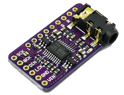
For audio output an I2S digital audio decoder (DAC) board is required. It is recommended to use an external DAC
| I2S DAC | ESP32 |
|---|---|
| BCLK | I2S_BCLK |
| LRCK/WS | I2S_WS |
| DIN | I2S_DOUT |
| SD | NC |
| GAIN | NC |
| VIN | 3V3 or 5V |
| GND | GND |
Internal DAC~
ESP32 has two 8-bit DAC (digital to analog converter) channels, connected to GPIO25 (Channel 1) and GPIO26 (Channel 2).
Those channels can be driven via the I2S driver when using the “built-in DAC mode” enabled with USE_I2S_NO_DAC
Commands~
| CMD DAC | action |
|---|---|
| I2SGain | 0..100 = sets the volume of the audio signal |
| I2SPlay | /file.mp3 = plays a .mp3 audio file from the file system, the systems blocks until sound is played+/file.mp3 = plays a .mp3 audio file from the file system, sound is played in a separate task not blocking the system |
| I2SRtttl | string = play Ring Tones Text Transfer Language (RTTTL) ringtones (requires defined USE_I2S_RTTTL) |
| I2SSay | text = speaks the text you typed (only English language supported) |
| I2STime | tells current Tasmota time in English (requires defined USE_I2S_SAY_TIME) |
| I2SWr | url = starts playing an mp3 radio stream, no blocking (requires defined USE_I2S_WEBRADIO)no parameter = stops playing the stream |
Audio Input~
For microphone input an I2S microphone must be connected.
I2S Microphone - standard mode~
Use command i2sconfig {"Rx":{"Mode":0}} to switch audio input to standard mode.
| I2S Microphone | ESP32 |
|---|---|
| SCK | I2S_BCLK |
| WS | I2S_WS |
| SD | I2S_DIN |
| L/R | GND |
| VDD | 3.3V |
| GND | GND |
If you're using only the microphone without a DAC you still need to set pin I2S_DOUT to an unused GPIO.
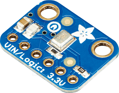
I2S Microphone - PDM mode~
Pulse density modulation (PDM) microphones are handled as I2S microphones in the ESP-IDF and need only two data wires in comparison to standard I2S microphones. They're used in ESP32-S3-BOX, Seeed Xiao Sense and others.
Use command i2sconfig {"Rx":{"Mode":1}} to switch audio input to PDM mode.
| Microphone | ESP32 |
|---|---|
| CLK | I2S_WS |
| DATA | I2S_DIN |
| L/R | GND |
| VDD | 3.3V |
| GND | GND |
| NC | I2S_DOUT |
| NC | I2S_BCLK |
When using PDM microphones the microphone CLK pin is configured as I2S_WS in Tasmota.
Commands~
ESP32 with PSRAM required!
i2sconfig {"Sys":{"Mp3Preallocate":1}} to turn on PSRAM allocation needed for MP3 encoding.
| CMD | Action |
|---|---|
| I2SMGain | 1..50 = sets the gain factor of the microphone |
| I2SRec | (requires defined USE_SHINE)/file.mp3 = starts recording a .mp3 audio file to the file system, no blockingno parameter = stops recording -? = shows how many seconds already recorded |
| I2SStream | (requires defined MP3_MIC_STREAM)1 = starts streaming .mp3 server at http://<device_ip>:81/stream.mp31 = stop the stream |
I2S Audio Bridge~
Starts an UDP audio service to connect 2 ESP32 devices as an audio intercom (an example).
Needs audio output and microphone on 2 devices (no PSRAM needed)
```arduino
build_flags                 = ${env:tasmota32_base.build_flags}
                              -DUSE_I2S_ALL
                              -DUSE_I2S_BRIDGE
```
| CMD bridge | action |
|---|---|
| I2SBridge | ip = sets the IP of the slave device0 = stop bridge1 = start bridge in read mode2 = start bridge in write mode3 = start bridge in loopback mode4 = set bridge to master5 = set bridge to slave6 = set microphone to swapped7 = set microphone to not swappedp<x> = sets the push to talk button where x is the button's GPIO pin number |
If a push to talk button is defined the bridge goes to write mode if the button is pushed and to read mode if the button is released