A4988 Stepper Motor Controller
This feature is not included in precompiled binaries
When compiling your build add the following to user_config_override.h:
#ifndef USE_A4988_STEPPER
#define USE_A4988_STEPPER    // A4988/DRV8825 stepper motor (+10k5 code)
#endif
This driver is used to control stepper-motors such as NEMA 17.
Configuration~
Wiring~
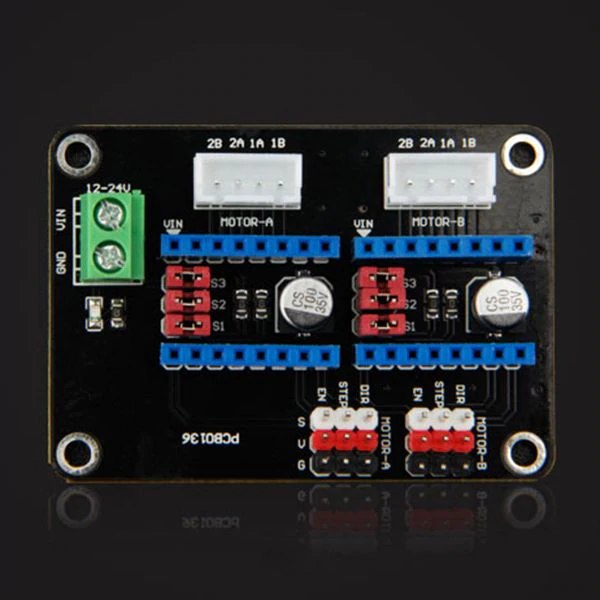
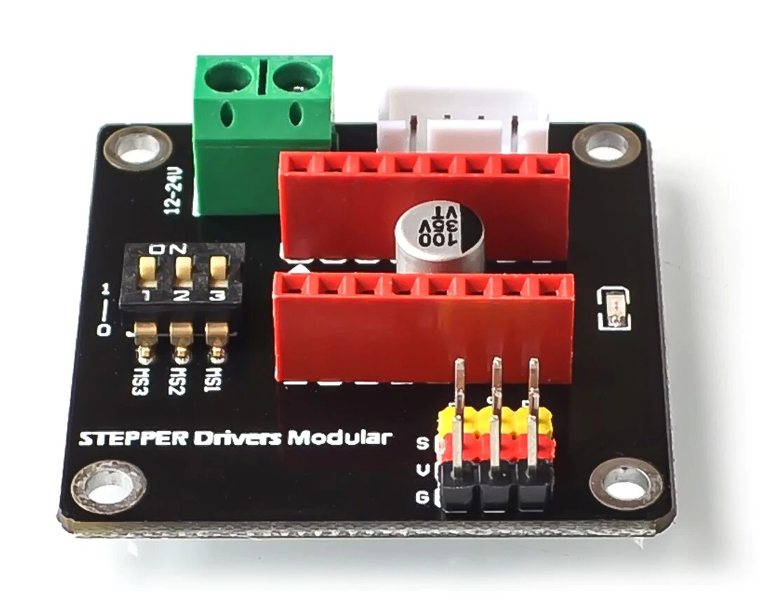
The driverboard has several connectors: powering the controller (3.3-5.0 V), input (+/-) & output (1a/1b/2a/2b), the motor (up to 35V/2A), and to control the circuit (in order at the control side of the board):
| Connector | Description |
|---|---|
| DIR | Direction of rotation |
| STEP | Initiate stepping |
| MS1 | Microstep increment select |
| MS2 | Microstep increment select |
| MS3 | Microstep increment select |
| EN | Enable the power supply for the motor |
| SLP | Sleep (bridge to RST) |
| RST | Reset (bridge to SLP) |
Tasmota Settings~
There are six GPIO components that should be configured to free GPIOs:
A4988 DIR (170)
A4988 STP (171)
A4988 ENA (172)
A4988 MS1 (173)
A4988 MS2 (174)
A4988 MS3 (175)
DIR and STEP signals. In such a configuration the motor will be permanently powered and microstepping will be set to 1/1 (full steps). A4988 Controller~
Detailed information about the A4988 controller can be found in the datasheet.
Microstepping Configuration~

DRV8825 Controller~
The DRV8825 is directly pin compatible with the A4988. The microstepping increment settings are different. Also, there is one additional option on the DRV8825.
Microstepping Configuration~

Operation~
Refer to the Stepper Motor Commands
MotorRPM is an imprecise setting due to the implementation method. Also, if the value is too high for the combination of chosen micro stepping increment (MotorMIS) and the number of steps the given motor needs for one revolution (MotorSPR), the motor will not turn but make a whining noise. You will have to experiment some to find the optimal combination for your use case.
Example Project~
The cheap auto-feeder for my cats broke. It was a fancy plastic-thingy with voice-recording-function & programmable to feed several times a day after playing back your voice (cats don't give a sh$7 about your voice - they come when they hear the food falling into the bowl). It was never precise - a concern for the amount of nutrition it gave the cats. And it was not reliable, as the torque of the internal moving mechanism was insufficient to spin the separator/proportioning wheel through the food reliably. In addition, the batteries were always drained in a day meaning very grumpy cats when we returned!
Thus the wish to install a high-torque stepper-motor (with shifting gear) was born. I could power it with mains instead of relying on a battery, control it over WiFi from my home automation hub. Tasmota now offers a way to do this!
The "TasmotaSmartCatFeeder" circuit consists of a WeMos D1 mini, an A4988 controller, and two power supplies (5V&12V). This all fits into the housing of the feeder and costs less than 50€!
Virtually everything which has to be moved or rotated can be done now using these cheap components. It can be a window, door, shutter, cat or dog flap, a solar panel which follows the sun, a moving spotlight, PTZ-camera, or whatever.
Wiring Diagrams~


Convert 28BYJ-48 to bipolar so that it works with this driver
Breakout Boards~