Shutters and Blinds~
Control blinds and roller shades connected to regular ON/OFF motors,stepper motors or position servos
Before starting you have to enable shutter support with SetOption80 1
There is a new enhanced ESP32 version you can enable with the following compiler option #define USE_SHUTTER_ESP32. Will be default in future versions for ESP32 after some testing. New features most likely only in ESP32 due to memory limitations in ESP8266. Current feature set:
- up to 16 shutters,
- up to 32 shutterbuttons,
- tilt definition with buttons.
- Configuration saved to filesystem.
- shuttersetup for Shelly plus 2PM to automatically measure open and close duration
Commands~
Complete list of commands is available at Blinds, Shutters and Roller Shades Commands.
Shutter Modes~
There are five shutter modes which define how the relays operate. Additionally you can define PulseTime on any relay to change the relay into a pulse relay where the pulse changes start/stop. At least for Shutter mode 1 an interlock is mandatory Interlock.
The examples below are for a ShutterRelay1 1 configuration (using Relay1 and Relay2).
Shutter mode 1 - Normal Operation
Relay1: UP/OFF, Relay2: DOWN/OFF
Interlock 1,2(Interlocked relay pair)Interlock ON
Shutter mode 2 - Circuit Safe (must be set manually)
Relay1: ON/OFF, Relay2: UP/DOWN
Interlock OFF
Shutter mode 3 - Garage Motors (must be set manually)
Relay1: OFF/DOWN PULSE, Relay2: OFF/UP PULSE
Shutter mode 4 - Stepper Motors (autodetect with PWM and COUNTER)
Relay1: ON/OFF, Relay2: UP/DOWN
- PWM: Stepper signal, COUNTER: Stepper position signal
- PWM and COUNTER defined
Shutter mode 5 - Servo Motors (PWM position based servo)
Relay1: ON/OFF, Relay2: UP/DOWN (optional not used)
- PWM: Stepper signal
PWMfrequency 200( This is mandatory for most relay to get correct PWM duty cylces)SetOption15 0(required to store value and make it reboot save)
Shutter mode 6 - Servo Motors 360° (PWM speed based servo)
Relay1: ON/OFF, Relay2: UP/DOWN (optional not used)
- PWM: Stepper signal
PWMfrequency 200( This is mandatory for most relay to get correct PWM duty cylces)SetOption15 0(required to store value and make it reboot save)
Wiring diagrams for Normal, Stepper motor, and Short Circuit-Safe configurations are available at the end of this page. Even if the shutter does not have two motors, three wires have to be connected.
Note
After setting the options for shutter mode, the device should be rebooted. Otherwise, the sliders won't be available in the web UI, and the ShutterOpenDuration<x>and ShutterCloseDuration<x> commands will report "Shutter unknown".
Issue Shuttermode command and check in console which ShutterMode is displayed: Issue Status 13 command and check in console how the shutter is defined
If you define Shuttermode 1 and there is NO interlock defined on the relay the driver go into ERROR state. To solve define INTERLOCK on the relay pair and set it to ON. Then define ShutterRelay1 again.
Shutter accuracy digits: 1
Shutter 0 (Relay:1): Init. Pos: 20000 [100 %], Open Vel.: 100 Close Vel.: 100 , Max Way: 20000, Opentime 10.0 [s], Closetime 10.0 [s], CoedffCalc: c0: 0, c1 200, c2: 200, c3: 0, c4: 0, binmask 3, is inverted 1, <span style="font-weight:bold;color:lime">ShutterMode 0</span>, motordelay 0
Operation~
Turning a device relay on or off directly (i.e., using Power) will function to affect a shutter's movement. In momentary mode (i.e., stepper motor), the relays start or stop the motor. The driver takes care of the direction and proper update of the shutter position.
The shutter reports its position and can also be sent to a dedicated position. ShutterPosition 0 means the shutter is closed and ShutterPosition 100 means the shutter is open. If you need the position values reversed (0 = open, 100 = closed), define and calibrate your shutter as documented below. Then tell Tasmota to reverse the shutter position meaning via the ShutterInvert<x> 1 command. All internal calculations are the same (the log output is the same). Only the interaction with the user and other systems changes. Now ShutterPosition<x> 0 will open the shutter and ShutterPosition<x> 100 will close the shutter.
| Function | ShutterInvert 0 | ShutterInvert 1 |
|---|---|---|
| Relay 1 | open shutter | open shutter |
| Relay 2 | close shutter | close shutter |
| Webbutton UP | open shutter | open shutter |
| Webbutton DOWN | close shutter | close shutter |
| Slider OPEN | open shutter | open shutter |
| Slider CLOSE | close shutter | close shutter |
| ShutterOpen | open shutter | open shutter |
| ShutterClose | close shutter | close shutter |
| ShutterPosition 100 | open shutter | close shutter |
| ShutterPosition 0 | close shutter | open shutter |
| Reported position when open | 100 | 0 |
| Reported position when close | 0 | 100 |
To set a value to all shutter you can use the index 0. For example ShutterPosition0 30 will move all shutters to 30%. The index 0 also works with all configuration items.
When SetOption80 1 is invoked you have to define Shutterrelay1 <value> to get started If possible to avoid any injury on unexpected movement all RELAYS should start in OFF mode when the device reboots: PowerOnState 0 
A maximum of four shutters per device are supported on ESP8266. The newer ESP32 can support up to 16 Shutters with 32 Relays. Nevertheless it might be required to add a GPIO expension board to get enough connectors.

To enable additional shutters, ShutterRelay<x> <value> must be executed for each additional shutter. Additional shutter declarations must be sequentially numbered, and without gaps (i.e., second shutter is 2, next shutter 3 and finally shutter 4).
Disabling a shutter in the middle of the defined set of shutters will disable all other higher numbered shutters. If the disabled shutter is restored, the higher numbered shutters previously declared will also be restored. When a shutter is added or removed, a list of the active shutters, with their parameters, is output to the log. If you intend to remove shutters, explicitly remove each one beginning with the highest numbered shutter.
With four shutters, eight Relay<x> components are needed. If manual operation switches (Switch<x> or Button<x> pairs) are also used, additional input GPIO are required. The ESP82xx device may not have enough free GPIO to support all the shutter connections required. A GPIO expander such as a PCF8574 or MCP230xx can be used with additional effort.
When using a switch for manual operation Switch<x> pairs should usually be set to SwitchMode<x> 2 (inverse follow) for proper switch behavior.
Any shutter positioning can be locked ShutterLock<x> 1. Once executed an ongoing movement is finished while further positioning commands like ShutterOpen<x>, ShutterClose<x>, ShutterStop<x>, ShutterPosition<x>, ... as well as web UI buttons, web UI sliders, and shutter buttons are disabled. This can be used to lock an outdoor blind in case of high wind or rain. You may also disable shutter positioning games by your children. Shutter positioning can be unlocked using ShutterLock<x> 0. Please be aware that the shutter can still be moved by direct relay control (i.e., Power<x>), or physical switches and buttons. Use the ShutterButton<x> command prior to ShutterLock to be able to lock buttons.
AutoSetup (Only Shelly plus 2PM, ESP32 based)~
The shelly plus has enough memory and a power measuring unit to setup the shutter in a convenient way. First you must callibrate your mechanical endstops of the shutter. Please do as descibed in the documentation of your shutter motors to ensure the shutter will stop at the endpoint correctly.
Then close the shutter until endstop is reached (repeat: backlog shuttersetopen;shutterclose until closed) - interlock 1,2 - interlock on - shutterrelay1 1 - shuttersetup (shutter will start moving....)
After setup is started the shutter will move to the upper endpoint and close again. If the shutter stops somewhere in the middle, try again. After setup you can use your shutter. Initial callibration for ShutterSetHalfway is 70. If you want to have it more accurate: backlog shutterclose;ShutterSetHalfway 50 and follow instructions below.
Calibration~
Shutter calibration video tutorial
Shutter calibration Google Spreadsheet
- Start your shutter in a closed position preferably. Set internal position to closed with
ShutterSetClose<x>. - Set the time needed to open the shutter completely with
ShutterOpenDuration<x>. - If the shutter opens more than needed, move it to the desired position with
ShutterSetPosition<x>then set the position to fully open (100) withShutterSetOpen<x>and decrease the open time. - Set the time needed to close the shutters with
ShutterCloseDuration<x>. - If the shutter does not close completely, open again and adjust close time.
- If it runs too long, move it back to desired closed position with
ShutterSetPosition<x>, reset to 0 withShutterSetClose<x>and decrease open time. - Alternate between opening and closing the shutter until you find out the exact times needed to get the same positions multiple times
After calibration is complete, you might want to enable an additional 1 second motor movement with ShutterEnableEndStopTime<x> 1 when the shutter is asked to move to its end positions (0% and 100%). With this you can guarantee that end positions are still reached in case of inaccuracies. Take care to disable this with ShutterEnableEndStopTime<x> 0 before further open or close duration measurements.
Motor Movement Delays~
Some motors need up to one second after power is turned on before they start moving. You can confirm if you are having this issue if opening and closing as a single action works properly but doing this in smaller steps result in a shift of the position.
Shutterposition<x> 30
Measure the shutter position. This is thereference_positionShutterposition<x> 80
Measure the shutter position. This is themax_positionShutterposition<x> 30
Return the shutter to starting position. This must be the same position as measured in step #1 (reference_position). If not,ShutterCloseDurationmust be adjusted.Shutterposition<x> 50Shutterposition<x> 70Shutterposition<x> 80
If you do not reachmax_positionyou have a motor delay problem. Measure the shutter position. This is thereal_max. Use this value in the calculation below.ShutterMotorDelay<x> <delay>
Motor<delay>calculation - fine tune in 0.05 second increments (e.g.0.65) as required.
<delay> = ((max_position-real_max) / 2) / (((100/80) * max_position) / ShutterOpenDuration)
Close the shutter and repeat this procedure until the motor delay is set properly.
Following defaults are pre-compiled into the code and can only be changed by compiling you own binary and use the user_config.override - In Failsafe-Mode the driver waits for 0.1sec to let the direction relay execute and be stable before switching on the power relay starting the movement. The time in [ms] can be changed by adding following line with a different value: #define SHUTTER_RELAY_OPERATION_TIME 100 // wait for direction relay 0.1sec before power up main relay
Coarse Positioning Calibration (Halfway point only)~
Some shutters need some time from totally closed until they begin moving the bottom-most part and opening. This often results in a shutter that is less than 50% open when the shutter has been operating for 50% of the set time. This can be corrected by using ShutterSetHalfway<x>. Use this procedure to calibrate the half-open position (alternatively there is a more exact calibration sequence using matrix values available in the next section):
ShutterClose<x>(confirm that the shutter is completely closed)ShutterSetHalfway<x> 50(reset to default)- Move the shutter to actual 50% open position.
- Use
ShutterPosition<x>to inquire the shutter's current position and record the value. This value is a percentage of the total opening (e.g.,63= 63% of opening). ShutterClose<x>ShutterSetHalfway<x> 63(using the value from step #4 above)Restart 1
Fine Positioning Calibration (Calibration Matrix)~
If you desire that the %-opening closely match what ShutterPosition<x> and web UI indicate, there is a granular calibration matrix available. Ensure that ShutterClose<x> and ShutterOpen<x> moves the shutter more or less to the limit positions and follow this procedure:
ShutterSetHalfway<x> 50(reset to default)ShutterCalibration<x> 30 50 70 90 100(reset to default)ShutterClose<x>- Move the shutter to each of the following opening percentages and measure the shutter's position for each.
ShutterPosition<x> 30(e.g., measurement =15)ShutterPosition<x> 50(e.g., measurement =50)ShutterPosition<x> 70(e.g., measurement =100)ShutterPosition<x> 90(e.g., measurement =150)ShutterPosition<x> 100(e.g., measurement =180)
- Finally, enter the position measurements as the calibration values:
ShutterCalibration<x> 15 50 100 150 180
ShutterCalibration<x> takes position measurements (not the time it takes to move). During calibration you position the shutter to an indicated percentage (e.g., 30%) of opening and measure the shutter position (e.g., 15). Use the same unit of measure for all your measurements (e.g., centimeters, inches, steps, etc.). After calibration ShutterPosition<x> 30 will move to 30% opening. This will be 30% from 180 (full open) == 54. Now the percentage match the percent in cm/inch/steps.
Notice that there is no calibration for the 10% position. On many shutters, there is no movement during the initial phase (i.e., nearly 10% of total time). Therefore the opening could be 0. This measurement would cause an execution DIV 0 exception. Therefore the first calibration point is 30%. In most cases this is not a large opening so the calibration will be near enough. Yes, until ~10%, the position will be a bit "off" but not enough for concern.
Motor Stop time~
When shutters change direction immediatly it can happen that there is a short circuit or at least high moments on the motors. Therfore the default time between a STOP and the next START of the shutter is 0.5s = 500ms. This allows in most cases the shutter to fully stop and then start from a static position. With Version 12.3 you can change the duration through shuttermotorstop 500 or any other value in ms. The value is for all defined shutters the same.
WARNING: If you control the relay DIRECT through buttons or switches and do not use shutterbuttons or a rule to decouple it, then the MOTOSTOPTIME cannot kick in. The Relay is ON before the shutterdriver can intercept.
Button Control~
When shutter is running in ShutterMode 1 (normal two relay up/off down/off), you already have basic control over the shutter movement using switches or buttons in the module configuration to directly drive the shutter relays. For short circuit safe operation ShutterMode 2 direct control of the relays will not give you a nice user interface since you have to 1st set the direction with one switch/button and 2nd switch on the power by the other switch/button. Because the button controll use multi-press events ensure that the "immediate action" is disabled: SetOption13 0 (default)
To have shutter mode independent button control over the shutter and not over its relays one can use the ShutterButton<x> command. It also introduces some more features, see below:
ShutterButton<x> <button> <func> <mqtt>
This assigns a Tasmota button <button> to control your shutter <x> having functionality <func>. The Tasmota button <button> must already be configured in the module configuration. You can assign multiple buttons to a single shutter. Any button can only control one shutter (beside the <mqtt> broadcast feature, see description below). Any press of the button while the shutter is moving will immediately stop the shutter.
One can remove all button control for shutter <x> by ShutterButton<x> 0.
The assigned button can have one of the following functionalities:
-
Setup for an "up" button:
ShutterButton<x> <button> up <mqtt>
Single press will move shutter to 100%, double press to 50% and triple press to 74%. Holding the button for more than the hold time (SetOption32) moves all shutters with same<grouptopic>to 100% when<mqtt>is equal to1. When<mqtt>is equal to0hold action of this button is same as single press. -
Setup for a "down" button:
ShutterButton<x> <button> down <mqtt>
Single press will move shutter to 0%, double press to 50% and triple press to 24%. Holding the button for more than the hold time (SetOption32) moves all shutters with same<grouptopic>to 0% when<mqtt>is equal to1. When<mqtt>is equal to0hold action of this button is same as single press. -
Setup for an "updown" button:
ShutterButton<x> <button> updown <mqtt>
Single press will move shutter to 100%, double press down to 0% and triple press to 50%. No hold action and no other shutter control by MQTT,<mqtt>is don't care here. -
Setup for a "toggle" button:
ShutterButton<x> <button> toggle <mqtt>Single press will toggle shutter, double press will move it to 50%. Be aware that the toggle select direction based on the current position. If the position is between 0..50% the shutter move to 100%. If the position is 51%..100% it moves to 0%. No hold action and no other shutter control by MQTT,<mqtt>is don't care here.
More advanced control of the button press actions is given by the following ShutterButton<x> command syntax:
ShutterButton<x> <button> <p1> <p2> <p3> <ph> <m1> <m2> <m3> <mh> <mi>
<button> ESP8266:1..4,ESP32:1..32 : Button number, 0/-: disable buttons for this shutter<p1> 0..100: single press position, t: toggle, -: disable, --0..100 or ++0..100 single press increment position<p2> 0..100: double press position, t: toggle, -: disable, --0..100 or ++0..100 double press increment position<p3> 0..100: triple press position, t: toggle, -: disable, --0..100 or ++0..100 tripple press increment position<ph> 0..100: hold press position, shutter stop after releasing the hold button if no group send <mh> is defined. If<mh> is 1 the release of the botton will NOT stop any shutter, t: toggle, -: disable<m1> 1: enable single press position MQTT broadcast, 0/-: disable<m2> 1: enable double press position MQTT broadcast, 0/-: disable<m3> 1: enable triple press position MQTT broadcast, 0/-: disable<mh> 1: enable hold press position MQTT broadcast, 0/-: disable<mi> 1: enable MQTT broadcast to all shutter indices, 0/-: disable
Parameters are optional. When missing, all subsequent parameters are set to disable.
ESP32 only: <p0..h> can be optional extended with a dedicated position of the tilt if a venetian blind is configured and supported. The position of the tilt can be added after the normal position with a / as seperator. This is optional. Example: shutterbutton1 1 100/-90 50/0 75/-90 100 - - 1 1. Tilt and position also support increment or decrement position from current state with --oder ++.
By a button single press the shutter is set to position <p1>. Double press will drive the shutter to position <p2> and triple press to position <p3>. Holding the button for more than the SetOption32 time sets the shutter position to <ph> max if button is hold until position. If the hold button is released during the shutter moves the shutter will stop. Any button action <p1> to <ph> can be disabled by setting the parameter to -. Independent from configuration <p1> to <ph> any press of the button while the shutter is moving will immediately stop the shutter.
Ensure that you set a value higher than 5 for SetOption32 (0.6 seconds is the minimum possible time). Lower values will not trigger the hold action for ShutterButton, and the shutter will not move.
Global steering of all your shutters at home is supported by additional MQTT broadcast. By any button action a corresponding MQTT command can be initiated to the <grouptopic> of the device. For single press this can be enabled by <m1> equal to 1, disabling is indicated by -. Double to hold MQTT configurations are given by <m2> to <mh>, correspondingly. When <mi> is equal to - only cmnd/<grouptopic>/Shutterposition<x> <p1..h> is fired. When <mi> is equal to 1, <x>=1..4 is used to control any shutter number of a Tasmota device having same <grouptopic>.
ShutterButton<x> <button> 100 50 74 100 0 0 0 1 1` is same as `ShutterButton<x> <button> up 1
ShutterButton<x> <button> 0 50 24 0 0 0 0 1 1` is same as `ShutterButton<x> <button> down 1
ShutterButton<x> <button> 100 0 50 - 0 0 0 0 0` is same as `ShutterButton<x> <button> updown 0
ShutterButton<x> <button> t 50 - - 0 0 0 0 0` is same as `ShutterButton<x> <button> toggle 0
Module WiFi setup, restart, upgrade and reset according to Buttons and Switches are supported "child and fool proof" only when no button restriction (SetOption1) is given and when all configured shutter buttons of that shutter are pressed 5x, 6x, 7x times or hold long simultaneously.
Remote Control~
Use any other Tasmota device with buttons or switches to control remotely a shutter using rules. Similar behavior as direct button control can be achieved by applying ShutterStopClose, ShutterStopOpen, ShutterStopToggle, ShutterStopPosition commands. They stop shutter movement if it is in motion and otherwise execute close, open, toggle or position commands.
Run this rule on another Tasmota device with a switch configured.
rule1 on switch1#state=2 do publish cmnd/%shutter-topic%/ShutterStopToggle endon
Using Rules~
Shutters can be used in rules to react on sensor data. Durign shutter operations data from all shutters is send every second to inform about current position, target, direction and the tilt (if supported). As usual with rules the compare operator can be used. Examples:
rule1 on shutter1#direction=0 do <echo shutter1 stopped> endon
rule1 on shutter2#position do var1 = %value% endon
rule1 on shutter#moving do <echo at least one shutter start moving> endon
rule1 on shutter#moved do <echo on shutter just stopped moving> endon
Additionally all commands are send as rules and can be used to trigger an action
rule1 on shutterposition1=0 do <echo shutter 1 is closing> endon
Specific Configuration~
Note
The PWM remains on even after the end position has been reached. The motor then permanently tries to hold the position and could thereby trigger noises or a slight "twitching". If this is not desired, you can switch off the PWM after reaching the end position with #define SHUTTER_CLEAR_PWM_ONSTOP.
Pulse Motors~
There are shutters that have two or three relays but only need a pulse to start or stop. Depending on the current situation a pulse will stop the shutter or send it into a specific direction. To use these kinds of shutters a PulseTime must be defined on each relay. The minimum setting that seems to make it work consistently is 2. A setting of 1 does not work. If the shutter moves too fast and does not react to a stop command, increase the setting to 3 or 4. If there is a dedicated relay for STOP and the other relays are only for OPEN and CLOSE you can enable this configuration e.g. on shutter one through: shutterStopRelay1 1. In this case a pulse will send to RELAY3 for stop and RELAY1 is for OPEN and RELAY2 for CLOSE only.
Stepper Motors~
Stepper motors can also be used to operate shutters and blinds. Additionally you can operate sliding doors with this configuration. Currently ESP32 12.0.2 does not support shutter with stepper motors. ESP8266 and ESP32 12.0.3+ supports up to 4 shutters.
Servo Motors~
Servos are small devices with typical 180° or 360" rotation movement. The position will be drived by the PWM duty cycle time. This will all automatically calculated
If you miss low angles (i.e 2°) you should be able to get this by changing the minimum ShutterPWMRange. If this does not help you can customize PwmFrequency. Normally for PWM servos, there is no calibration required, but you have the option to do a calibration. Check the documentation for shuttercallibration. Maybe ShutterSetHalfway is already enough. Otherwise you can do a fine granular calibration.
If you change the shutteropenduration/closeduration the servo will operate slower, but now the servo also achieves small angle changes.
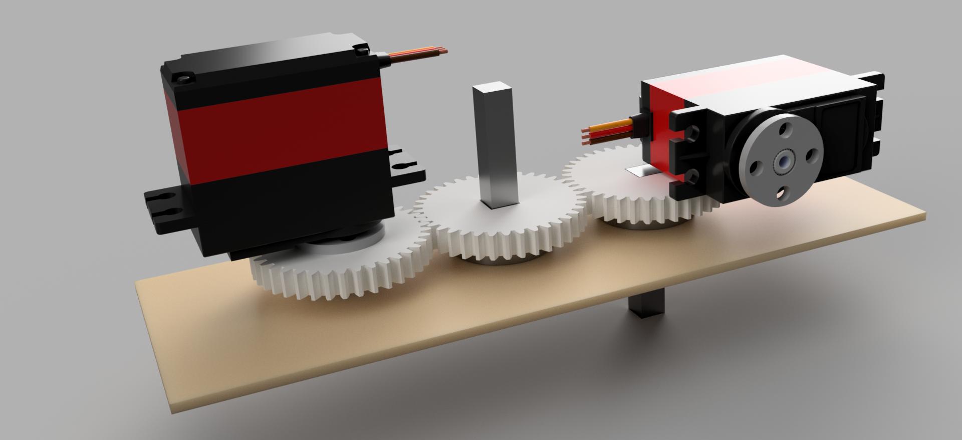
Servo controlled by PWM pulses. The angle to which the servo should be set is regulated by the pulse width. The servo has no direction of rotation (clockwise or counterclockwise), but only the rotation angle of the output shaft.
Servo controlled by PWM pulses. The angle to which the servo should be set is regulated by the pulse width. The servo has no direction of rotation (clockwise or counterclockwise), but only the rotation angle of the output shaft.
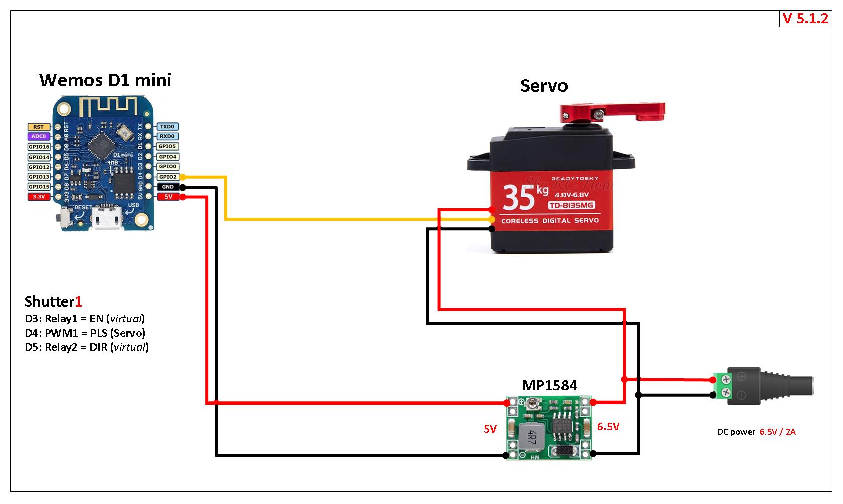
To operate a servo requires signal uses:
EN(enable) turn on / off servo.PLS(pulse) for controls rotation angl.DIR(direction) only shows the direction of rotation, but does not control it.
More information:~
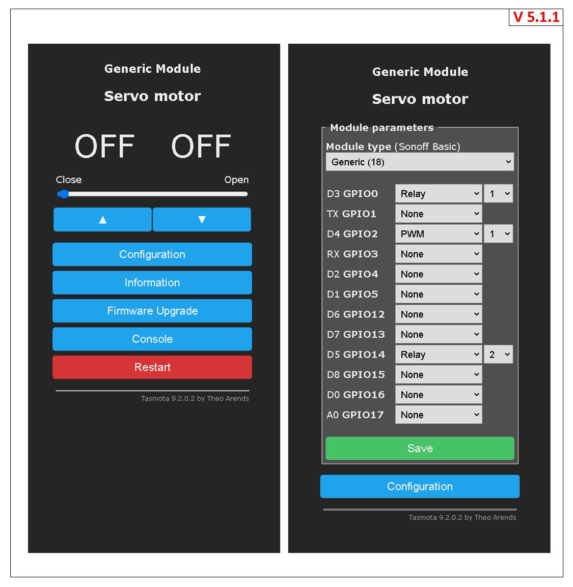
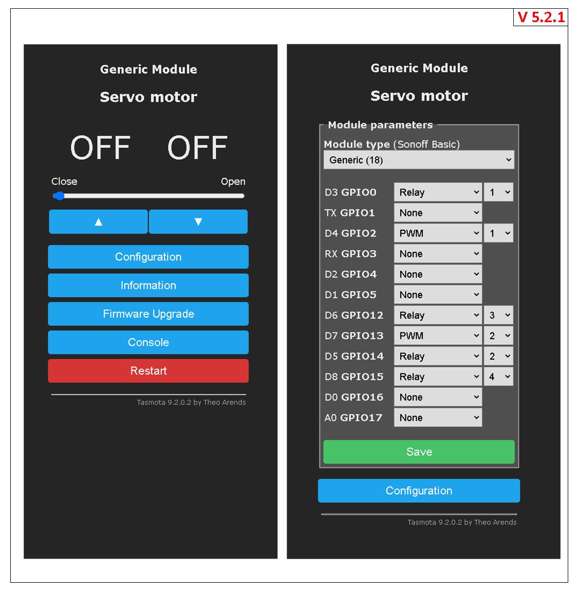
Example configuration~
EN and DIR are on Relay1 and Relay2 respectively. Remember to use a non-inverse relay for the enable signal. The PLS signal is assigned as a PWM<x> component where <x> matches the number of the shutter (e.g., PWM1 for Shutter1).
The PWM frequency must be set with the PWMfrequency 200 command. The frequency setting is a global setting all PWM components on the device. This means that all shutters on the device will operate at the same speed.
Using the ShutterMotorDelay command to provide a slow increase / decrease in speed. This causes the driver to ramp the speed up and down during the defined duration. The change of the ShutterMotorDelay does NOT change the distance the shutter makes. This is very convinent to trim the accelerate and decelerate rate without changeing the distance.
ShutterOpenDuration and ShutterCloseDuration define the open / close time. By changing the times you adjust the speed of the servo output shaft. ShutterOpenDuration and ShutterCloseDuration can be different.
Using the ShutterPwmRange command to set the pulse width range. The calculation of parameters for ShutterPwmRange is obtained by dividing by 5 the minimum and maximum values of the pulse width range.
Note!~
Even within the same servo model, there may be manufacturing tolerances that result in a different operating range of pulse lengths. For accurate operation, each specific servo must be calibrated: through experiments, it is necessary to select the correct range that is specific to it.
For example the pulse width range for different servos:
- Servo MG90 (180°): pulse width range 544 - 2400microseconds,
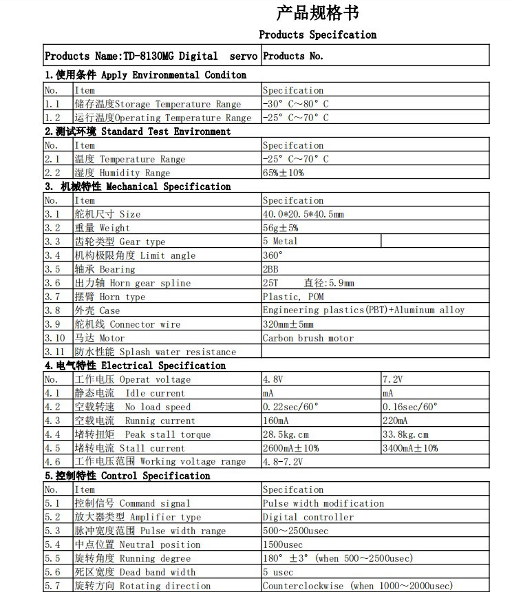
ShutterPwmRange109, 480 - Servo TD-8130MG (180°): pulse width range 500 - 2500microseconds,
ShutterPwmRange100, 500
Servo datasheet:~
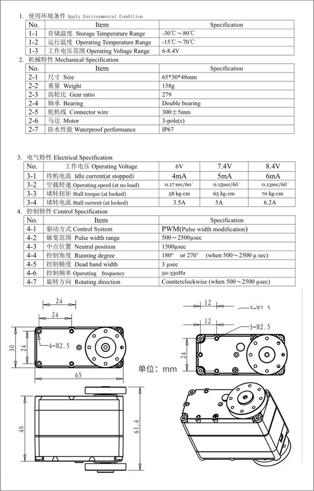
How to use it:~
| Wemos Pin | GPIO | Component | Servo Signal |
|---|---|---|---|
| D3 | 0 | Relay1 | EN |
| D4 | 2 | PWM1 | PLS |
| D5 | 14 | Relay2 | DIR |
Important: Please do the first start after configure without any load on the servo. If the shutterposition and servo position are not in sync the servo will change to the start position without speed and acceleration control like later in normal operation.
- Run commands in the console to run the "Shutter" mode (you must first configure the GPIO!):
SetOption80 1// enable Shutters support.
shutterrelay1 1// Define that RELAY1 is for ON/OFF and PWM1 drive position
Shuttermode 5// enable Shutter mode for servo.
PWMfrequency 200// this is a global variable for all Servos.
SetOption15 0// to control the storage of values. - Run commands in the console to configure the motor operation:
ShutterPwmRange1 100, 500//this is a global variable for all Servos.
ShutterOpenDuration1 0.5// define the open time, in seconds.
ShutterCloseDuration1 0.5// define the close time, in seconds.
ShutterMotorDelay1 0.2// servo does not like abrupt start / stop.
Restart 1 - Run commands in the consolee to test the motor operation:
ShutterOpen1// to open the SERVO#1.
ShutterStop1// to stop the SERVO#1.
ShutterClose1// to close the SERVO#1. - Perform the shutter calibration (optional).
Motor Wiring Diagrams~
One Shutter~
- Diagram v512: Minimum configuration for one servo, power on continuously.
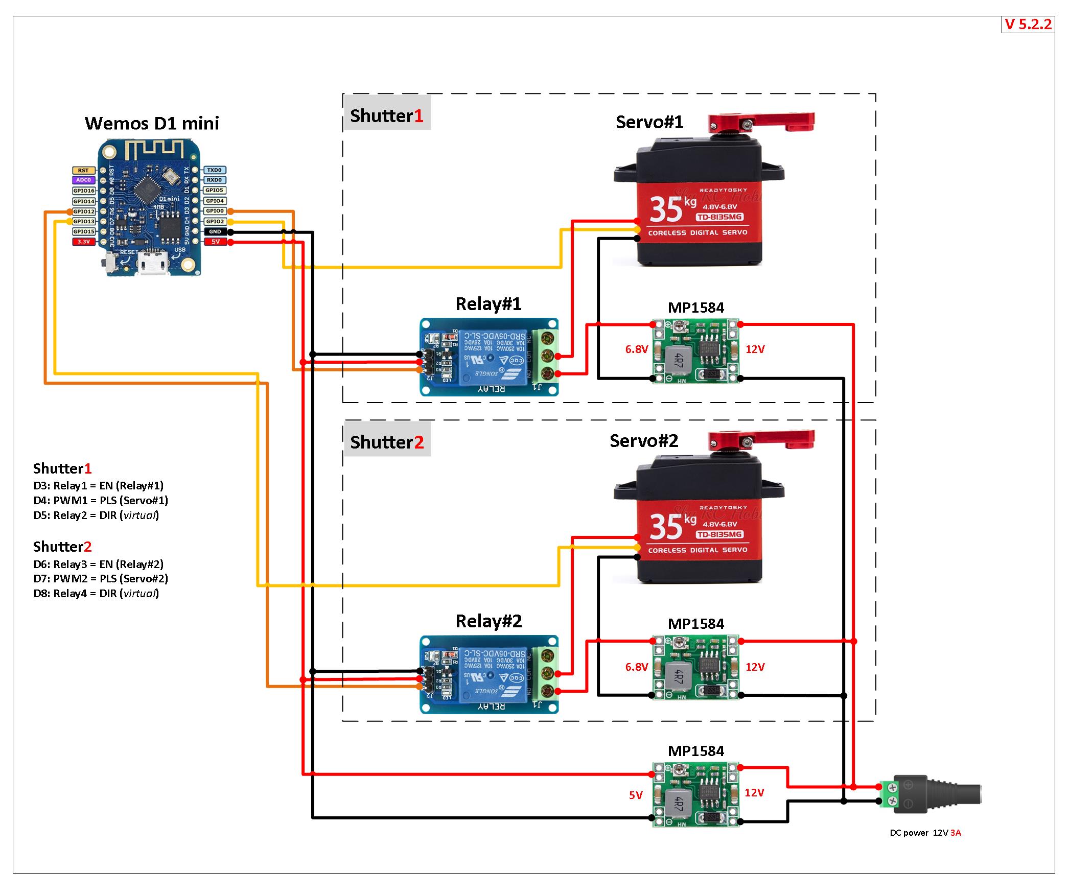
Dual Shutter~
- Diagram v522: Optimal configuration for two servos, power is supplied through the relay.
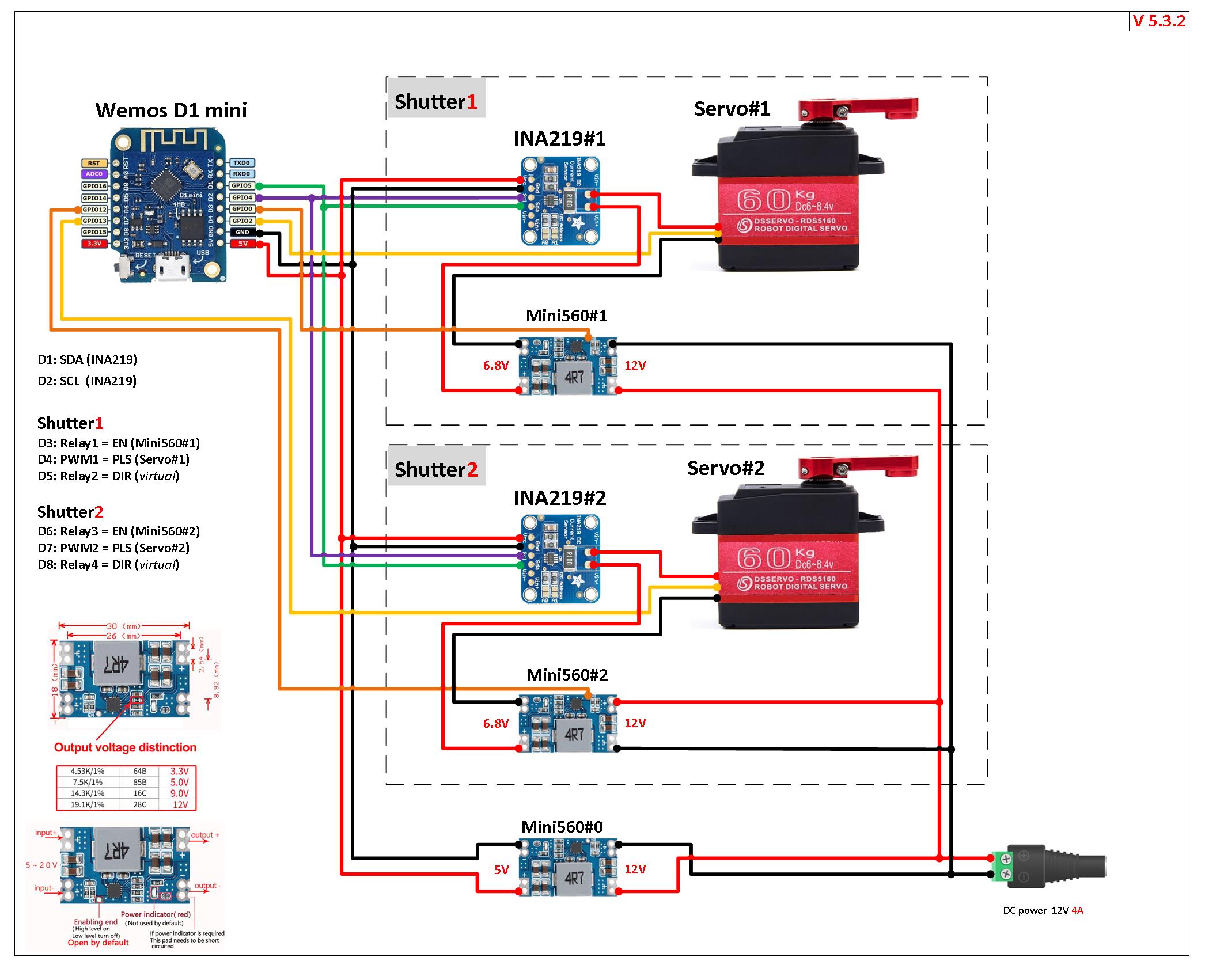
- Diagram v532: Maximum configuration for two servos, power is supplied via the relay only if the servo is running. Current control for each servo drive via INA219.
Additional Information:~
DC Motors~
Smooth RAMP-UP and RAMP-DOWN Support~
Servos and Steppers also have a velocity control. With ShutterMotorDelay<x> 1.5 you can define a 1.5second soft start/stop before the device reaches it final moving speed. Usefull for moving heavy items like doors.
using normal Motors~
Short Circuit safe wire configuration with a PCF as digital I/O. Avoid electrical shortage also on wrong configuration.~

using Stepper Motors~
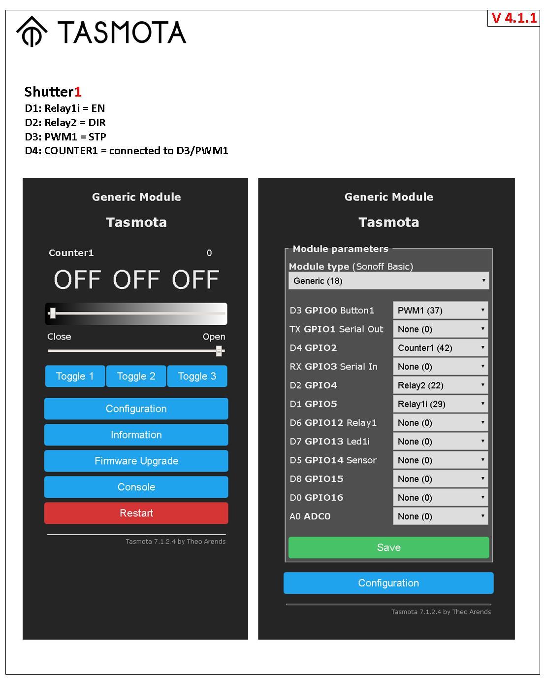
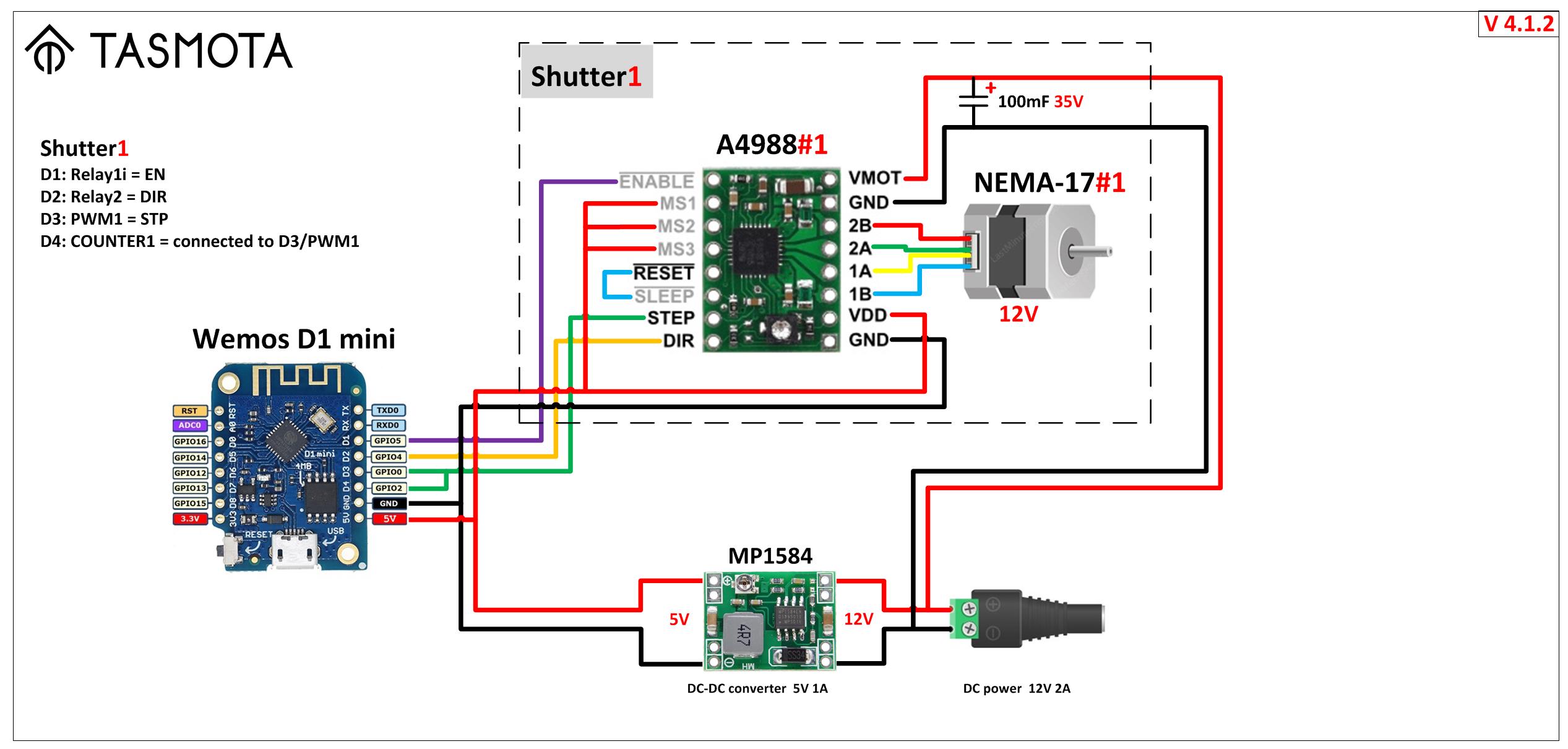
Stepper motors can be used to operate shutters and blinds. The configuration is very similar to the Circuit Safe (Shuttermode 1) configuration. To operate a stepper motor requires driver module such as the A4988 and uses EN (enable), DIR (direction), STP (Stepper) for controls. If everything is defined correctly Shuttermode 4 will be reported at boot time. ESP8266 only supports one shutter with steppermotors. ESP32 up to 4.
Tasmota supports a maximum of four shutters with one stepper motor per shutter simultaneously. In very rare conditions where two or more shutters simultaneously move the last mm it can happen than one shutter moves to far.
- Stepper drivers configuration tutorials:
- Modifying a 28BYJ-48 12V stepper motor from unipolar to bipolar tutorial
- Bill of Materials
Example configuration~
EN and DIR are on Relay1i and Relay2 respectively. Please be aware to use the inverse relay for the enable signal.
The STP signal is assigned as a PWM<x> component where <x> matches the number of the shutter (e.g., PWM1 for Shutter1). The shutter feature adjusts the PWM frequency to operate the motor for proper shutter operation. The stepper motor frequency setting is a global setting all PWM components on the device. This means that all shutters on the device will operate at the same speed. Therefore no PWM devices other than shutters can be connected to the same Tasmota device. To get in the UI the light sliders hidden you must set setoption15 0
The frequency of the PWM can be changed from 1000Hz to any value up to 10,000Hz. The command ShutterFrequency globally changes this. Be aware that most 12V operated motors cannot work faster than 2,000Hz. 5,000Hz.10,000Hz is possible by increasing the supplied voltage to 24V and use ShutterMotorDelay to allow a slow speed up/speed down. The maximum voltage of the A4988 is 36V. The TMC2208 is much more silent than the others but also significant slower and does not like high frequencies. For example, the speed at 24V is half o A4988
Finally a GPIO must be assigned as Counter1. This counter is used to keep track of the steps and send the stepper to the correct position. The Counter1 GPIO must be connected to the PWM1 GPIO. Otherwise the stepper and your shutter will run continually or freeze up randomly.
Only bipolar stepper motors may be used (see above).
You must properly configure the stepper motor driver (see above).
ShutterOpenDuration and ShutterCloseDuration can be different. Shutter with Stepper motors always match positions exact. There is no need to vary ShutterOpenDuration and ShutterCloseDuration. Anyhow, if you decrease ShutterCloseDuration the Shutter will close with a higher speed on a virtual higher ShutterFrequency if possible. Same vice versa.
You can define a soft start/stop by defining a ShutterMotorDelay. This causes the driver to ramp the speed up and down during the defined duration. The change of the ShutterMotorDelay does NOT change the distance the shutter makes. This is very convenient to trim the accelerate and decelerate rate without changing the distance.
| Wemos Pin | GPIO | Component | Stepper Signal |
|---|---|---|---|
| D1 | 5 | Relay1i | EN |
| D2 | 4 | Relay2 | DIR |
| D3 | 0 | PWM1 | STP |
| D4 | 2 | Counter1 | STP |
a) Set ShutterMode 4
Backlog PulseTime1 0; PulseTime2 0 // for relay Relay1i and Relay2
Interlock OFF // this is a global variable for all Relays or at least the RELAYS NOT in the Interlock group setoption15 0 // remove any light sliders from the UI PWM1 and COUNTER1 defined
b) Enable Shutters
SetOption80 1 // this is a global variable for all Shutters
c) Configure Shutter 1 and test ShutterMode 1 is working
ShutterRelay1 1 // for relay Relay1i and Relay2
d) Set the stepper motor speed (optional setting)
ShutterFrequency 1500 // this is a global variable for all steppers (1000rpm by default)
e) Set at least a small ramp-up/ramp down period 1.0 second (optional)
ShutterMotorDelay1 1.0 // Stepper do not like infinite momentum. Ramp up/down speed allow much higher frequencies.
f) Restart Tasmota
Restart 1
g) Test the shutter
ShutterOpen1
ShutterStop1 // to stop the STEPPER1
ShutterClose1
ShutterInvert1 // to change the direction of rotation of the STEPPER1
h) Perform the shutter calibration
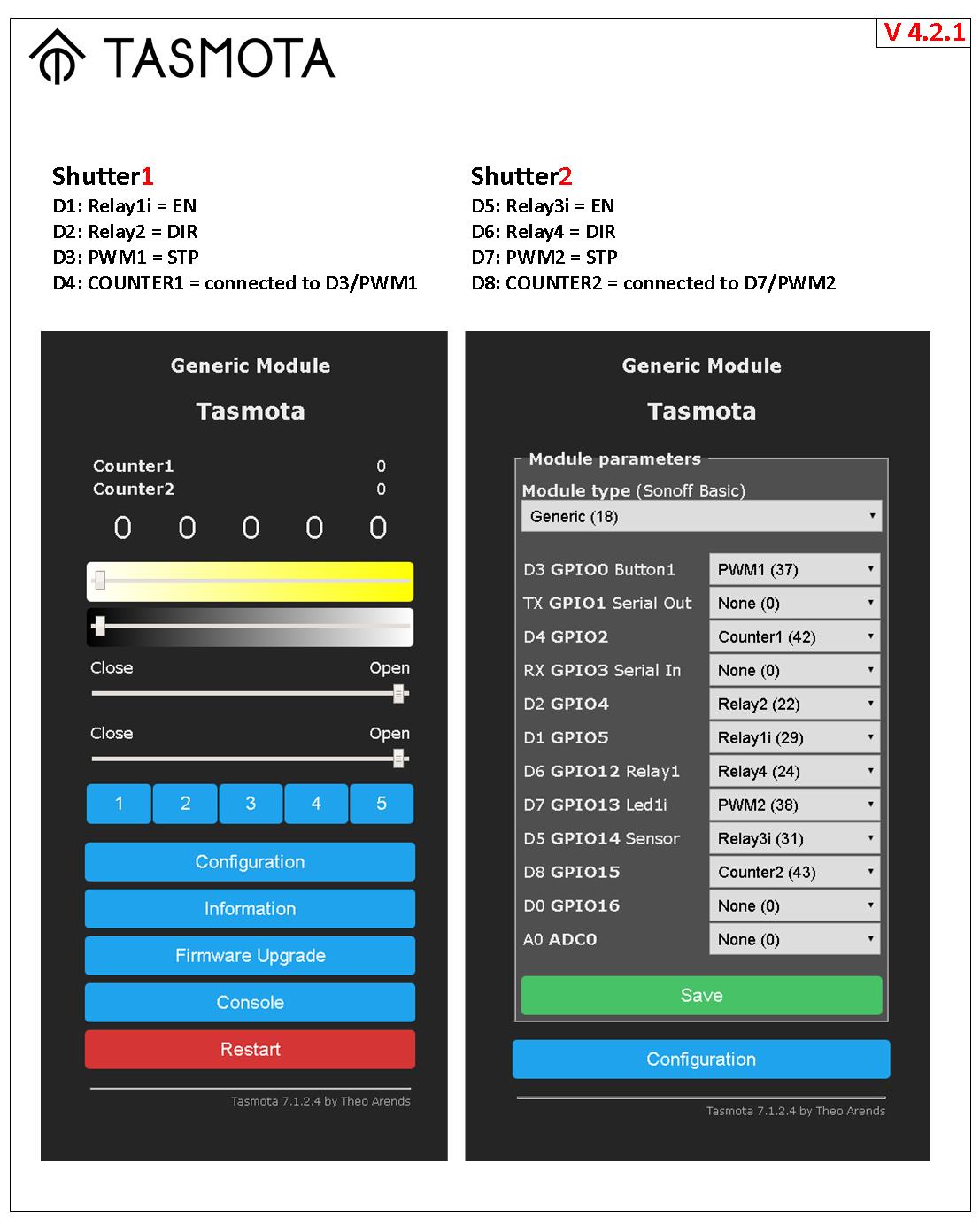
Configuration for additional shutters~
You must first set up the first shutter and only then the next.
| Wemos Pin | GPIO | Component | Stepper Signal |
|---|---|---|---|
| D5 | 14 | Relay3i | EN |
| D6 | 12 | Relay4 | DIR |
| D7 | 13 | PWM2 | STP |
| D8 | 15 | Counter2 | STP |
a) Set ShutterMode 4
Backlog PulseTime3 0; PulseTime4 0 // for relay Relay3i and Relay4
PWM2 and COUNTER2 defined
c) Configure Shutter 2 and test ShutterMode 1 is working
ShutterRelay2 3 // for relay Relay3i and Relay4
b) Restart Tasmota
Restart 1
d) Test the shutter
ShutterOpen2
ShutterStop2 // to stop the STEPPER2
ShutterClose2
ShutterInvert2 // to change the direction of rotation of the STEPPER2
e) Perform the shutter calibration
Motor Wiring Diagrams~
One Shutter~
 - Diagram v412: simple universal setup. For example, the control of horizontal curtain or vertical shutters, blinds adjuster or window opener, pet feeders, opening of a water tap for watering the lawn, rotating table for subject photography, opening the ventilation flap, PTZ camera, 3D Scanner Table, linear Actuator.
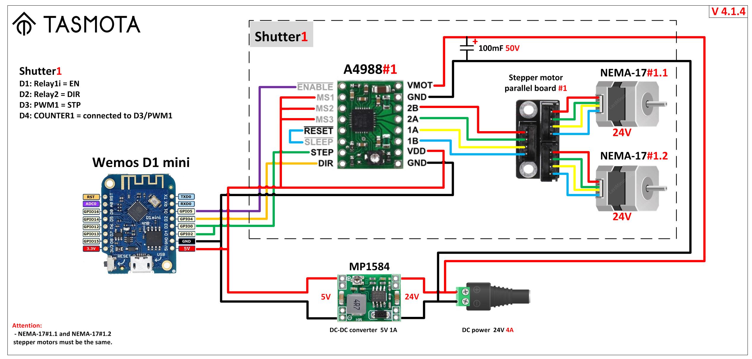
 - Diagram v414: parallel setup is to run two parallel steppers motors from the same controller. For example, to control a large and heavy hanging screen for an LCD projector, or two curtains at once on one large window.
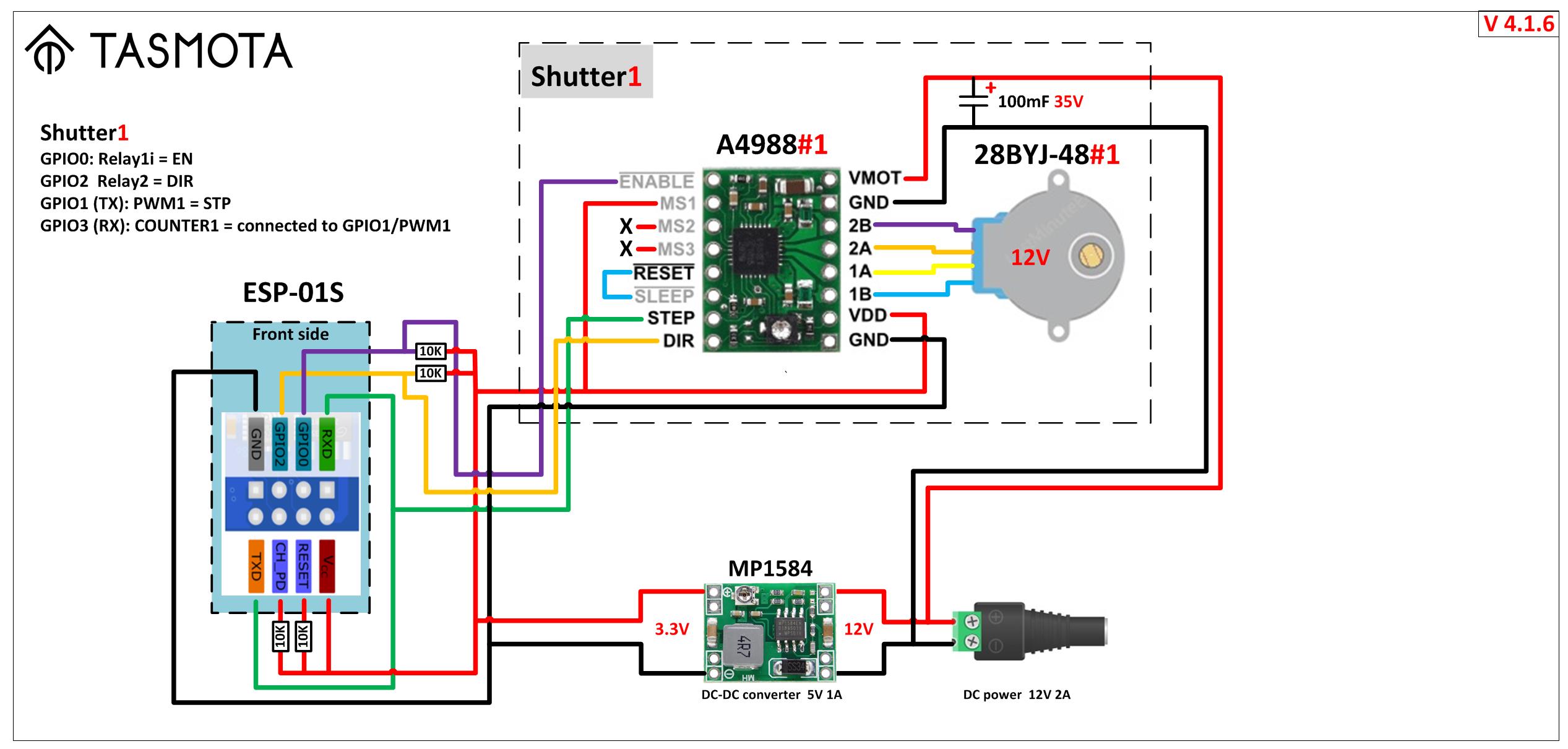
 - Diagram v416: minimum setup size. For example, for small curtains located in a limited space.
2 Shutters~
 - Diagram v422: parallel setup is to run two shutters and independent control of two stepper motors from one controller. For example, to control two independent curtains.
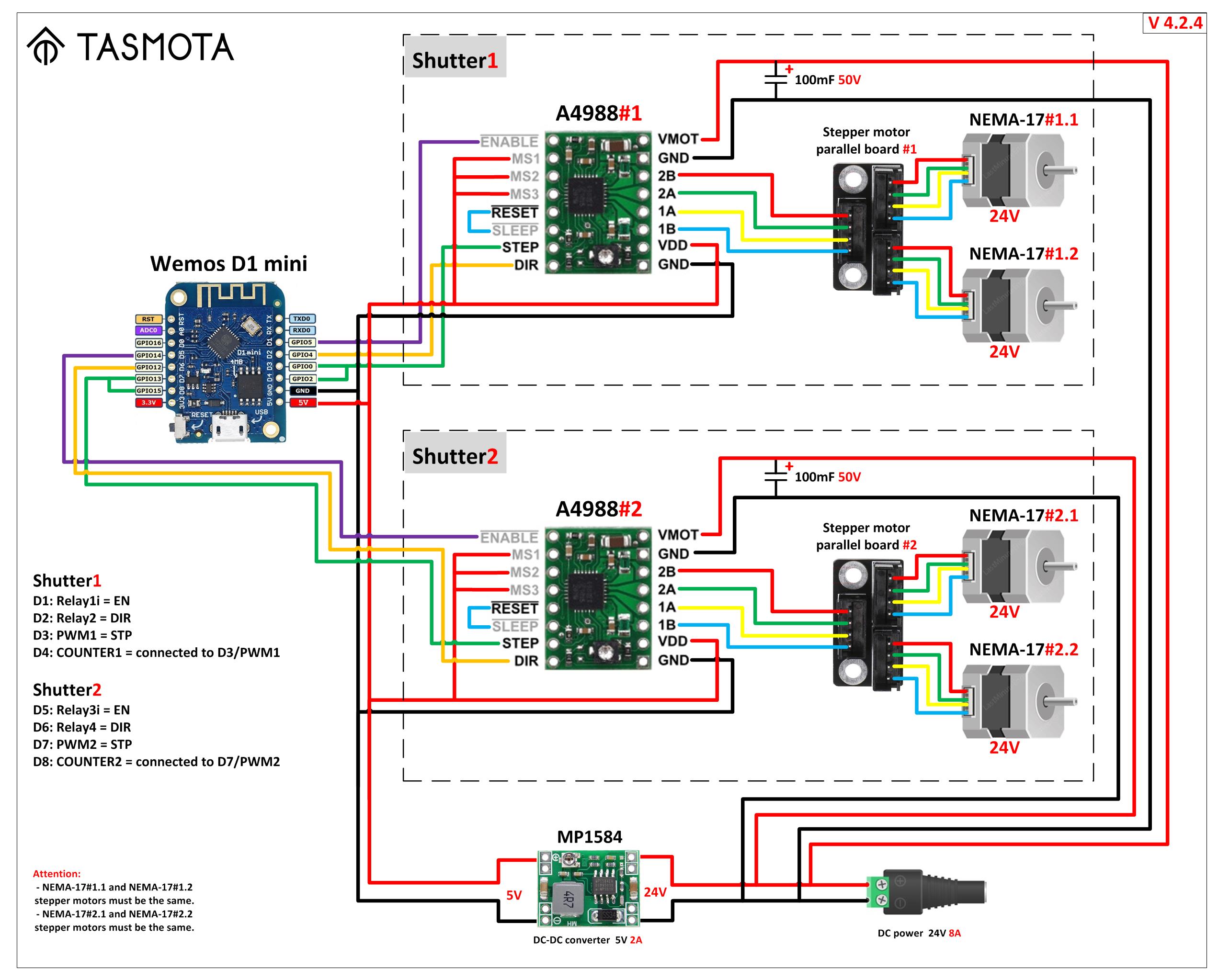
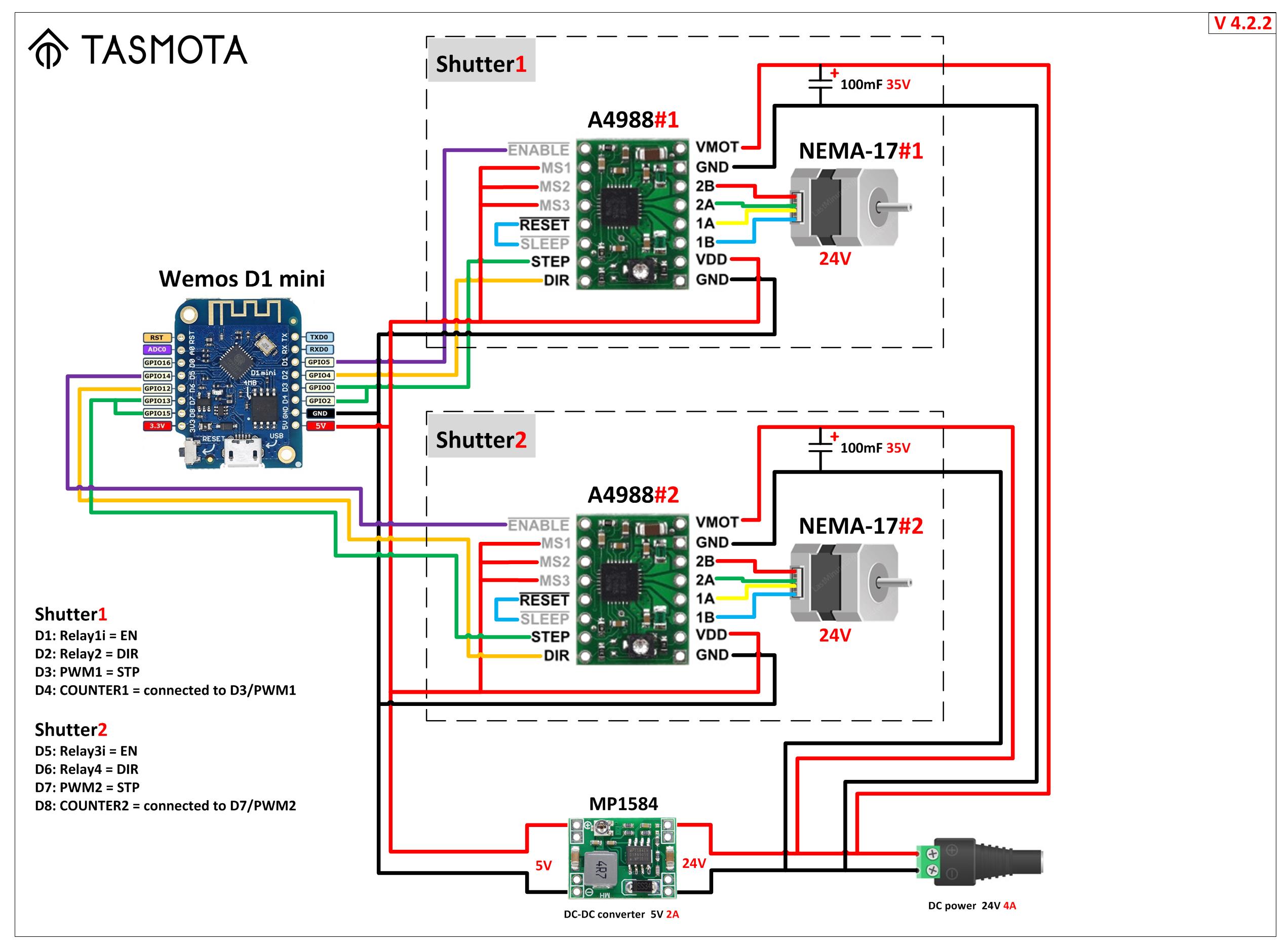 - Diagram v424: big parallel setup is to run two shutters and independent control of two pairs of stepper motors from one controller. For example, to control four curtains on one very large window.
Bill of Materials~
- ESP8266 Boards:
- Wemos D1 mini
- NodeMCU
- ESP-01S
- Stepper motors (NEMA 17):
- Standard
- 5:1 Planetary Gearbox
- Stepper motors (28BYJ-48):
- Standard
- Stepper Drivers:
- A4988
- DRV8825
- TMC 2208
- Stepper Motor Control Development Boards:
- x1 board
- x2 board
- DC-DC Step Down Power Supply Module:
- MP1584EN
- LM2596
- XL4015
- Power Supplies (AC-DC):
- DC 12V 2.5A
- DC 12V 4A
- DC 24v 4A
- Aluminum Capacitors:
- 35V 100UF
- 35V 10UF
- Motor Testing PWM Signal Generator:
- 1 type
- 2 type
using Sonoff Dual R2~
If using a Sonoff Dual R2, use the following Template:
{"NAME":"Sonoff Dual R2","GPIO":[17,255,0,255,0,22,18,0,21,56,0,0,0],"FLAG":0,"BASE":39}
Checklist~
- Ensure that the first relay opens the shutter
- Ensure that the second relay closes the shutter
- Set
ShutterRelay<x> - Set
ShutterOpenDuration<x> - Set
ShutterCloseDuration<x> - Set
ShutterSetHalfway<x>(optional) - Set
ShutterInvert<x>(optional) - Set
ShutterInvertWebButtons<x>(optional) (eg. useful for horizontal awnings) - If the shutter uses a pulse motor instead of a motors with one wire for each direction (i.e., duration based), define
PulseTime<x> 2on both relays. The driver's behavior will change to a pulse motor that needs pulses to start and stop.
Rules~
Tasmota rule triggers:
Shutter<x>#Positionis triggered at start, during and at the end of movement reporting actual position (%value%=0-100)Shutter<x>#Directionis triggered at start, during and at the end of movement reporting actual direction (%value%:-1=close direction,0=no movement,1=open direction)Shutter<x>#Targetis triggered at start, during and at the end of movement reporting current target (%value%0-100)Shutter#Movingis triggered during movement and just before moving (shutter independently). If VAR<x> is set to 99 then this trigger will be executed BEFORE the shutter starts. You can start the shutter after rule execution by setting VAR<x> to 0 or wait 10seconds before the timeout kicks in. After the movement with shutter#moved theVARmust be set back to 99 and the initial rule must be enabled again. The initial rule has to be defined to run ONCE. EXAMPLE: power3 on and wait 2sec before start. After movement: power offrule1 on shutter#moving=1 do backlog power3 on;delay 20;var1 0 endon rule1 5 rule2 on shutter#moved do backlog power3 off;var1 99;rule1 5 endon rule2 1Shutter#Movedis triggered at end of movement (shutter independently)Shutter<x>#Button<button>=0is triggered whenbuttonis holdShutter<x>#Button<button>=<n>is triggered whenbuttonis pressedntimesShutter<x>#Button0=0is triggered when all buttons of that shutter are hold simultaneouslyShutter<x>#Button0=<n>is triggered when all buttons of that shutter are pressed simultaneouslyntimes
Examples
- Publish a message with the position of the shutter:
Rule1 ON Shutter1#Position DO Publish status/%topic%/level {"%value%"} ENDON - Open/Close or set a specific position for a shutter. This example drives the second shutter to the same position as the first shutter:
Rule1 ON Shutter1#Position DO ShutterPosition2 %value%" ENDON
Jarolift Shutter Support~
Jarolift shutters operates by the 3 commands up/stop/down. Compile with the KeeLoq Option and provide the extracted master keys to communicate. Please see KeeLoq description how to do that. After this create a rule to allow the shutter to control the Jarolift devices. Shutter must be in ShutterMode 0.
Rule1 On Power1#state=0 DO KeeloqSendButton 4 endon On Power2#state=0 DO KeeloqSendButton 4 endon on Power1#state=1 DO KeeloqSendButton 8 endon on Power2#State=1 DO KeeloqSendButton 2 endon
Venetian Blind Support~
All time based shutters (not stepper, pwm) can be enhanced with Venetian Blind functionality. The configuration need following parameters: angle of blinds during opening phase, angle of blinds during closing phase. This are the max and the min values of the venetian blinds (e.g. opening at 0° - closing at 90°). Additionally the runtime is required from min to max. This is typically 1-2sec. The resolution of the time is 0.05sec. Duration in [sec] must be multiplied by 20. e.g. 1.2sec => 1.2 x 20 = 24. To open and close the tilt you must define the angle for CLOSE and the angle for OPEN of the tilt (be careful about the correct order, refer to the following example)
Example: - Angle of the slats when the blind is opening: 0° - Angle of the slats when the blind is closing: 90° - Time needed to flip in 1/20 seconds (1 second = 20): 40 - Desired angle of the slats when set to CLOSE : 90° - Desired angle of the slats when set to OPEN : 0°
ShutterTiltConfig1 0 90 40 90 0
Tilt configuration can be set for every shutter independently. The tilt can be set with one of the following commands: shuttertilt1 open set tilt to defined open angle shuttertilt1 close set tilt to defined close angle shuttertilt1 20 set tilt to 20° angle
If the shutter is moved from one position to another position the tilt will be restored AFTER the movement. If the shutter is fully opened or fully closed the tilt will be reset. This means there is no tilt restore at the endpoints. If you want to restore the tilt at the endpoint you have two options to do that: - use a backlog command e.g. backlog shutterclose1; shuttertilt1 open - use shutterposition1 0,90 with an optional position of the tilt as a second parameter
Similar to shutterchange to make relative movements there is also a shuttertiltchange with the same behavior.
If the shutter is operated with wall buttons or the web interface and stopped during a tilte change before the shutter starts moving the NEW tilt position is stored. Now any additional position movements will restore this new tilt position. This makes is possible with small ON/OFF to change the tilt and with long ON/OFF to change the position and retain the tilt after movement.
Similar to shutterposition there is a minimum runtime of the motor required that TASMOTA can control. This is 0.2sec. Because the tiltmovement from one position into the other takes often about 1sec it is very common that you cannot make small tilt changes of 10° or sometimes even 20".