Buttons and switches: why the difference and how to configure them
A typical device usually has at least one button (exception being bulbs and some lights) to control the power state(s). Additional buttons and switches can be wired to a free GPIO and configured in Module or Template settings.
Note
Other than relays/lights, Tasmota does not publish the state of components (switches, buttons, sensors, etc.) in real-time. State of components is transmitted automatically each TelePeriod via the SENSORS message.
Choose GPIO configuration~
All board are not born equal so does your own diy realisations, you might have choosen to put your own pull-up resistors , or had an inverted logic on your button input.
The first thing is to correctly select the Button or Switch variant accordingly in the "Configure module" or "Configure template" menu. the variants supported by ESP8266 are following :
- Button : Button active low, internal pull-up resistor
- Button_n : Button active low, no internal pull-up resistor (_n like NoPullUp)
- Button_i : Button inverted, active high with internal pull-up resistor
- Button_in : Button inverted, active high no internal pull-up resistor (_in like Inverted NoPullUp)
- Switch : Switch with internal pull-up resistor
- Switch_n : Switch without pull-up resistor
the ESP32 supports all forementionned variants plus :
- Button_d : Button with internal pull-down resistor
- Button_id : Button inverted, active high with internal pull-down resistor
- Switch_d : Switch with internal pull-down resistor
Button vs. Switch~
A button (also called a push-button) is a momentary or non-latching switch which causes a temporary change in the state of an electrical circuit only while the switch is pressed. An automatic mechanism (i.e. a spring) returns the switch to its default position immediately afterwards, restoring the initial circuit condition.
A switch (more precisely a latching or toggle switch), when activated by the user, remains in that state until activated again.
Learn more about buttons and switches in this video.
Both have a similar function, but Tasmota distinguishes between a "Button" and a "Switch" in other ways.
Switch~
In Tasmota a Switch is any switch or push-button additionally connected to a free GPIO. Some possibilities include:
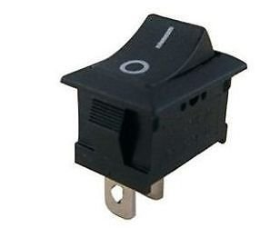
- mechanical toggle switch - also called a rocker switch
- capacitive touch switch
- reed switch
- PIR sensor - even though it's technically a sensor it is configured as a switch in Tasmota
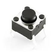
- mechanical push-button
By default a switch toggles the corresponding power state (e.g., Switch1 controls Power1). Every time the switch gets flipped the power state of the relay toggles.
If you want to detach switches from relays read here.
Warning
If you define a switch with a number higher than available power outputs it will default to controlling Power1. Example: Switch4 on a device with Power1 and Power2 will control Power1.
And now, to make everything completely confusing: A push-button can be configured as a Switch and a toggle switch can be configured as a Button. Configuring a toggle switch as a Button is not recommended!
SwitchMode~
To change the behavior of a physical input peripheral configured as a Tasmota Switch<x> component, whether a toggle switch or a momentary switch (i.e., a push-button), use the SwitchMode command. If there is more than one Switch<x> component, use SwitchMode<x> where <x> is the number of your switch from the Tasmota GPIO configuration.
SwitchMode, as the name implies, applies ONLY to GPIO configured in Tasmota as a Switch<x> component. SwitchMode has NO impact on the behavior of GPIO configured as Button<x> components. SwitchMode sets the desired behavior of a Switch<x> component based on whether it's a switch or a push-button (i.e., a momentary switch) that is physically connected to the GPIO.
SwitchMode 0-
Default mode
Set switch to toggle mode (
0 = TOGGLE,1 = TOGGLE).Tasmota sends
TOGGLEcommand each time the state of the circuit changes (closing or opening). In case of a push button attached Tasmota will send aTOGGLEcommand when pressed and anotherTOGGLEcommand when released.Example
When the button is pressed, toggle the power to ring the doorbell; when the button is released, ring the doorbell again.
SwitchMode 1-
Set switch to follow mode (
0 = OFF,1 = ON)At the time when the circuit is closed, Tasmota will send
ONand opening the circuit sendsOFF.Tip
You want to use
SwitchMode 1when connecting a toggle switch (e.g. a classic light switch) to your device. This way the "software switch" will mirror the state of the "hardware switch". If the real switch is in the "ON" position, the state in Tasmota isONas well. SwitchMode 2-
Set switch to inverted follow mode (
0 = ON,1 = OFF)At the time when the circuit is closed, Tasmota will send
OFFand opening the circuit sendsON.Tip
When connecting a momentary switch (i.e., a push-button) you will want to use
SwitchMode 3..7. SwitchMode 3-
Set push-button mode (
0 = TOGGLE,1 = ON(default))Tasmota will send a
TOGGLEcommand when the button is pressed (closing the circuit). When the button is released (opening the circuit) nothing will happen. Default state is OFF and when pressed it's ON. (This trigger is known as rising-edge) SwitchMode 4-
Set inverted push-button mode (
0 = OFF(default),1 = TOGGLE)Tasmota will send a
TOGGLEcommand when the button is released (opening the circuit). When pressing the button (closing the circuit) nothing will happen. Default state is ON and when pressed it's OFF. (This trigger is known as falling-edge) SwitchMode 5-
Set push-button with long press mode (
0 = TOGGLE,1 = ON(default),long press = HOLD)Tasmota will send a
TOGGLEcommand when the button is released (opening the circuit). When pressing the button (closing the circuit) nothing will happen. Default state is ON and when pressed it's OFF. When held for the time set inSetOption32(default = 4s), Tasmota sendsHOLD(useSwitch<x>#state=3in rules). SwitchMode 6-
Set inverted push-button with long press mode (
0 = OFF(default),1 = TOGGLE,long press = HOLD)Tasmota will send a
TOGGLEcommand when the button pressed (closing the circuit). When the button is released (opening the circuit) nothing will happen. Default state is OFF and when pressed it's ON. When held for the time set inSetOption32(default = 4s), Tasmota sendsHOLD(useSwitch<x>#state=3in rules).Long press or hold can be used in conjunction with rules to create additional features or to control another Tasmota device
SwitchMode 7- Set toggle push-button mode. Same as
SwitchMode 0. SwitchMode 8-
Set switch to multi change toggle mode (
0 = TOGGLE,1 = TOGGLE,2x change = HOLD).Same as
SwitchMode 0but when the state of the circuit changes within 0.5s twice noTOGGLEcommands are send but Tasmota sendsHOLD(useSwitch<x>#state=3in rules).Warning
When you change switch states fast (within 0.5s) some extra actions can be triggered using rules. ON and OFF power states are only changed when there is no second switch change within 0.5s.
SwitchMode 9-
Set switch to multi change follow mode (
0 = OFF,1 = ON,2x change = HOLD)Same as
SwitchMode 1but when the state of the circuit changes within 0.5s twice noOFF/ONcommands are send but Tasmota sendsHOLD(useSwitch<x>#state=3in rules).Warning
When you change switch states fast (within 0.5s) some extra actions can be triggered using rules. ON/OFFpower state is only changed when there is no second switch change within 0.5s.
SwitchMode 10-
Set switch to multi change inverted follow mode (
0 = ON,1 = OFF,2x change = HOLD)Same as
SwitchMode 2but when the state of the circuit changes within 0.5s twice noON/OFFcommands are send but Tasmota sendsHOLD(useSwitch<x>#state=3in rules).Warning
When you change switch states fast (within 0.5s) some extra actions can be triggered using rules. ON/OFFpower state is only changed when there is no second switch change within 0.5s.
SwitchMode 11-
Set switch to pushbutton with dimmer mode incl. double press feature
Note
Setoption32 must be smaller than 64, when you use switchmode 11 and 12 !!
Tasmota will send a
TOGGLEcommand when the button is pressed for a short time and then is released (useSwitch<x>#state=2in rules).When pressing the button (closing the circuit) for a long time (set in
SetOption32), Tasmota will send repeatedINC_DEC(increment or decrement the dimmer) commands for as long as the button is pressed (useSwitch<x>#state=4in rules).Two different
CLEARcommands are available. An immediateCLEARcommand is send upon button release - no delay (useSwitch<x>#state=7in rules).Releasing the button also starts an internal timer (time is set in
SetOption32). When released for the time set inSetOption32, Tasmota will send a 'delayed'CLEARcommand (useSwitch<x>#state=6in rules).If the button is pressed again before the timeout, Tasmota will send an
INVcommand. TheINVcommand is for the controlling software (Home Assistant) to switch between incrementing and decrementing the dimmer (useSwitch<x>#state=5in rules).If button is pressed twice (within time set in
SetOption32), Tasmota will send aDOUBLEcommand. Note that this doesn't change behaviour of other switch states. So along with theDOUBLEcommand,TOGGLEcommand will also be fired twice upon a double press (useSwitch<x>#state=8in rules).If the button is pressed only once and shorter than the time set in
SetOption32, Tasmota will also send thePOWER_DELAYEDcommand (useSwitch<x>#state=10in rules) when no second press occurs within time set inSetOption32. You can use this for triggering single press events instead of usingTOGGLEif you want to use single and double press individually (sinceTOGGLEis triggered for both single and double press). Keep in mind, that this event is delayed in comparison toTOGGLE.Tip
Possible use case: using rules to create additional features or to control another Tasmota device.
SwitchMode 12-
Set switch to inverted pushbutton with dimmer mode incl. double press feature. Same as
Switchmode 11but with inverted behaviour.Note
Setoption32 must be smaller than 64, when you use switchmode 11 and 12 !!
SwitchMode 13-
Set switch to "push to on" mode (
1 = ON,0 = nothing)Tasmota will send an
ONcommand when the button pressed (closing the circuit). When the button is released (opening the circuit) nothing will happen. Switch off usingPulseTime. SwitchMode 14-
Set switch to inverted "push to on" mode (
0 = ON,1 = nothing)This mode is useful with PIR sensors
SwitchMode 15-
Send only MQTT message on switch change. This will stop the switch from controlling power outputs, and you get no state values for rules.
tele/tasmota/SENSOR = {"Time":"2021-01-01T00:00:00","Switch1":"OFF"}
tele/tasmota/SENSOR = {"Time":"2021-01-01T00:00:00","Switch1":"ON"}
SwitchMode 16- Send only MQTT message on inverted switch change. This will stop the switch from controlling power outputs, and you get no state values for rules.
tele/tasmota/SENSOR = {"Time":"2021-01-01T00:00:00","Switch1":"ON"}
tele/tasmota/SENSOR = {"Time":"2021-01-01T00:00:00","Switch1":"OFF"}
Also see
SetOption114below.
Button~
For Tasmota, a Button is typically a momentary push-button (or a capacitive touch button in some light switches). By default a button toggles the corresponding power state. Every time the button gets pressed a relay or light changes its Power state (ON or OFF). Besides toggling the Power state, a button is also used to activate multi press button functions, to do long press (HOLD) actions, or send messages to different MQTT topics.
 Depending if you are using a push-to-make button or push-to-break button, as well as connecting the button between GPIO and GND or GPIO and VCC, different configurations are possible. The diagram beside (click to enlarge) present the various options:
To ignore default button behaviour of controlling power outputs you can:
- use
SetOption73 1 - use
ButtonTopic - define a rule which triggers on
Button<x>#State. Take note: If the rule trigger only certain states, default behaviour is suppressed only for those states.
Make Button1 publish its value to stat/custom-topic/BUTTON and not control Power1
Backlog ButtonTopic 0
Rule1 on Button1#state do Publish stat/custom-topic/BUTTON %value% endon
Rule1 1
Multi-Press Functions~
Multipress functions for 2 and more presses cannot be changed using SetOptions or rules.
Danger
If you have changed ButtonTopic, SetOption1, SetOption11 or SetOption13 some of the listed functionality will be changed or removed.
Note
Button1 can directly control up to five relays. The number of the activated relay corresponds to the number of button presses and this feature is not present in the other buttons. When ButtonTopic is set to default 0 a button will always send its state for rules. In the below, you can enable SetOption4 to replace the "RESULT" part of the topic.
1 short press- Toggles the power state. This will blink the LED once and send an MQTT status message like
stat/tasmota/POWER = ONor another one likestat/tasmota/RESULT = {"Button<x>":{"Action":"SINGLE"}}when SetOption73 is enabled. The button state for rules is2(10ifSetoption73is enabled). 2 short presses- When using Button1 toggles the second power state (if available on the device). This will blink the LED twice and send an MQTT status message like
stat/tasmota/POWER2 = ONor another one likestat/tasmota/RESULT = {"Button<x>":{"Action":"DOUBLE"}}when SetOption73 is enabled. The button state for rules is11. 3 short presses- When using Button1 toggles the third power state (if available on the device). This will blink the LED three times and send an MQTT status message like
stat/tasmota/POWER3 = ONor another one likestat/tasmota/RESULT = {"Button<x>":{"Action":"TRIPLE"}}when SetOption73 is enabled. The button state for rules is12. 4 short presses- When using Button1 toggles the fourth power state (if available on the device). This will blink the LED for times and send an MQTT status message like
stat/tasmota/POWER4 = ONor another one likestat/tasmota/RESULT = {"Button<x>":{"Action":"QUAD"}}when SetOption73 is enabled. The button state for rules is13. 5 short presses- When using Button1 toggles the fifth power state (if available on the device). This will blink the LED five times and send an MQTT status message like
stat/tasmota/POWER5 = ONor another one likestat/tasmota/RESULT = {"Button<x>":{"Action":"PENTA"}}when SetOption73 is enabled. The button state for rules is14. 6 short presses- Set
WifiConfig 2(start Wi-Fi Manager). Can be disabled usingSetOption1 1. For security reasons, you should change backWifiConfigafter that.
Long press~
-
There are two separate functions associated with a button long press based on how long it is held:
- When held continuously for 40 seconds (Configurable with SetOption32, value is 10x the configured hold time) Tasmota will reset to firmware defaults and restart.
- If enabled, button pressed for 4 seconds (Configurable with SetOption32) creates a HOLD action and send an MQTT status message like
stat/tasmota/RESULT = {"Button<x>":{"Action":"HOLD"}}when SetOption73 is enabled. The button state for rules is3. With SetOption73 enabled, when the button is released you'll also get MQTT messages likestat/tasmota/RESULT = {"Button<x>":{"Action":"CLEAR"}}and button state15.
If ButtonRetain has been enabled the MQTT message will also contain the MQTT retain flag.
Danger
When a button is configured as inverted or with a Switchmode that keeps it as ON while depressed it activates the reset to firmware defaults function. Change the Button configuration or SwitchMode to avoid repeated reset to defaults or use
Setoption1 1to disable that function.Warning
If you define a button with a number higher than available power outputs it will default to controlling
Power1. Example: Button4 on a device with Power1 and Power2 will controlPower1.
ButtonTopic~
ButtonTopic 0-
Default option
By default a button controls the corresponding power state and doesn't send any MQTT messages itself.
No MQTT message will be published on account of the new button state. The message you see in console is the new power state that is controlled and not the button state.
ButtonTopic 1-
Sets MQTT button topic to device %topic%.
When changing the state of the button an MQTT message is sent to the device topic with the payload according to
SwitchModeset.Example
Device topic tasmota with
SwitchMode 3yields the following message:MQT: cmnd/tasmota/POWER = ONNotice the cmnd instead of the stat at the beginning.
This is the same as sending an MQTT command to this device, the device power state will be set to the defined state.
ButtonTopic <value>-
Set button topic to a custom topic (32 characters max).
This will send an MQTT message to a custom defined topic similarly to option 1.
Example
For example, we set the topic to tasmota02 with
ButtonTopic tasmota02. WithSwitchMode 1the device yields the following message:MQT: cmnd/tasmota02/POWER = TOGGLEIf you have another device with the topic tasmota02 this action will toggle its power state while not affecting anything on the tasmota device.
ButtonTopic Summary~
ButtonTopic 0 controls the power state directly. ButtonTopic 1 sends an MQTT message to the device topic. This sets the state of the devices power state accordingly. ButtonTopic <value> sends an MQTT message command to the custom topic. This does not change the state of the devices power state.
When a Button is set to a different topic than 0 is not possible to use Button<x>#State as a trigger for rules.
Changing Default Functionality~
If a ButtonTopic (and if SetOption1 1) or SwitchTopic 1 is defined (and SwitchMode is set to 5 or 6) and a button is pressed longer than defined Key Hold Time (SetOption32 default 4 seconds) an MQTT message like cmnd/%topic%/POWER HOLD will be sent. HOLD can be changed with StateText4.
Command SetOption11 allows for swapping the functionality between the SINGLE and DOUBLE press of the push button.
These changes result in the following:

Example~
You can control a ceiling fan from a Sonoff Touch: If your standard topic of Sonoff Touch is light and the ceiling fan topic is ceilingfan issue these commands on the Sonoff Touch to activate the double press feature.
ButtonTopic ceilingfan
SetOption11 1
AC Frequency Detection Switch~
Some devices, such as BlitzWolf BW-SS5 or Moes MS-104B, use mains frequency detection on their switch inputs. Whenever the connected switch or button is pressed there are 50/60 Hz pulses on the switch input. Inside the switch there's a frequency detection circuit which is connected to a GPIO of the ESP8266 chip which counts those pulses. Prior to Tasmota 8.4 this kind of switching was handled using Counter sensors and scripting which is now simplified.
You can imagine this algorithm as a leaking bucket. Every pulse adds water to the bucket (little more than leaking out in a cycle), but the water is dripping countinously. If the bucket is full, we will treat the switch on. If there's no pulses, the bucket will be empty, and the we will turn off the switch. The size of the bucket is the debouncing time which controls the sensitivity of the algorithm. If the mains frequency is 50 Hz, a whole AC wave is 20 msec long (for 60 Hz it's about 17 msec; 1000 / frequency if we want the result in milliseconds). The exact frequency is not really important, because we add more water for every pulse.
After you have assigned a Switch<x> to the GPIO connected to the AC frequency detection circuit use the 'SwitchDebounce' command to set the number of pulses required for the switch to be recognized as on or off. For example: SwitchDebounce 69 will turn the switch on after three pulses and turn it off after three missing ones (3 * 20 msec is 60 and the last digit must be 9 to activate the AC detection). You will probably have to experiment with the values depending on your AC frequency and the devices frequency detection implementation.
Once the feature is enabled you can use this switch as any regular switch!
Detach Switches with...~
SetOption114~
When SetOption114 1 all switches are detached from their respective relays and will send MQTT messages instead in the form of {"Switch<x>":{"Action":"<state>"}}.
Example
When switch one is toggle to "ON":{"Switch1":{"Action":"ON"}}
SwitchMode 15~
With command SwitchMode<x> 15 you can decouple Switch<x> from its power output and it will instead send MQTT messages in the following format:
MQT: tele/tasmota/SENSOR = {"Time":"2021-01-01T00:00:00","Switch1":"OFF"}
MQT: tele/tasmota/SENSOR = {"Time":"2021-01-01T00:00:01","Switch1":"ON"}
StateText command. You can change the default "Switch1" text using SwitchText<x> command. For example: SwitchText1 Garage_Door_State
When Setoption114 1 is used together with SwitchMode<x> 15, Tasmota Integration in Home Assistant will create a binary sensor in HA using the Default text "String1" or the text mentioned in the SwitchText command.
Rules~
Use rules to send messages to different MQTT topics or send commands to other Tasmota devices when switch state (defined by SwitchMode) changes.
To ignore the default behaviour define a rule which triggers on Switch<x> for all state changes or on Switch<x>#State for specific state changes. If a rule matches only certain states, default switch behaviour is suppressed only for those states.
Example
Make Switch1 publish any value change to stat/custom-topic/SWITCH1 and not control Power1
Backlog SwitchMode 1; SwitchTopic 0
Backlog Rule1 on Switch1#state do Publish stat/custom-topic/SWITCH1 %value% endon; Rule1 1
SwitchTopic~
Warning
When using SwitchTopic 1 or 2 (or ButtonTopic 1 or 2) and your MQTT broker becomes unavailable, Tasmota falls back to default SwitchTopic 0 (or ButtonTopic 0), which is not optimal.
To avoid this, we recommend using first two options instead.
If you still need to use SwitchTopic read on!
SwitchTopic 0-
Default mode
By default a switch controls the corresponding power state and doesn't send any MQTT messages itself.
No MQTT message will be published on account of the new switch state. The message you see in console is the new power state that is controlled and not the switch state.
SwitchTopic 1-
Sets MQTT switch topic to device %topic%
When changing the state of the switch an MQTT message is sent to the device topic with the payload according to
SwitchModeset.Example
Device topic tasmota with
SwitchMode 3yields the following message:MQT: cmnd/tasmota/POWER = TOGGLENotice the cmnd instead of the stat at the beginning.
This is the same as sending an MQTT commands to this device, the device power state will be set to the defined state.
SwitchTopic <value>-
Set switch topic to a custom topic (32 characters max)
This will send an MQTT message to a custom defined topic similarly to option 1.
In the following example, we set the topic to
tasmota02withSwitchTopic tasmota02.Example
Device topic tasmota with
SwitchMode 1and custom topic tasmota02 yields the following message:MQT: cmnd/tasmota02/POWER = ONIf you have another device with the topic tasmota02 this action will turn on its power while not affecting anything on the tasmota device.
SwitchTopic Summary~
SwitchTopic 0 controls the power state directly. SwitchTopic 1 sends an MQTT message to the device topic. This sets the state of the devices power accordingly. SwitchTopic <value> sends an MQTT message command to the custom topic. This does not change the state of the devices power.
For a practical application of everything mentioned in this article read about this excellent LEGO nightstand switch project.