CC253x Zigbee module~
CC2530, CC2531, and CC2538 are Texas Instruments system-on-chips (SoCs) for Zigbee communication
Any Texas Instruments CC253x series based module can serve as a coordinator if it has Z-Stack firmware flashed. See list of supported modules with their pinouts and flashing instructions since they are different for each device.
Info
Z-Stack Home 1.2 is fully supported in Tasmota allow the use of CC2530, CC2531, and CC2538 Zigbee MCU chips/SoCs/modules. There is also preliminary support for Z-Stack 3.x as of Tasmota v9.2.0.4 which allow the use of more powerful Zigbee MCU chips/SoCs/modules from Texas Instruments CC26x2 and CC13x2 series (example CC2652P, CC2652R, CC2652RB, CC1352P and CC1352R).
Info
You cannot use a Zigbee adapter in USB mode! Flash it with Z-Stack firmware and it will work in serial mode. You will have to wire the Zigbee MCU chips/SoC/modules for serial communication using TX and RX pins or solder-pads. USB port cannot be used for communicating with a Zigbee MCU chip/module.
Wi-Fi Adapter~
Using an ESP82xx device such as a Wemos D1 Mini or a NodeMCU to flash the CC2530 is a lower cost alternative than using a single purpose CC_DEBUGGER.
In normal operation two free GPIOs are needed for the serial communication with the CC2530.
Custom PCBs~
These PCBs make all the connections required to flash the CC2530 and to run Z2T:
SuperHouse.tv~
Jon Oxer created a custom PCB to connect a Wemos D1 Mini and a CC2530 board (with or without CC2591).
Complete module


Charles (aka hallard)~
Mainly based on Jon Oxer PCB, Charles created a new one with multi connect option for CC2538 + CC2592 to connect a Wemos D1 Mini/Raspberry PI or even with USB a CC2538 with CC2592 module. This works with awesome support of ZStack V3 by @s-hadinger
Complete module
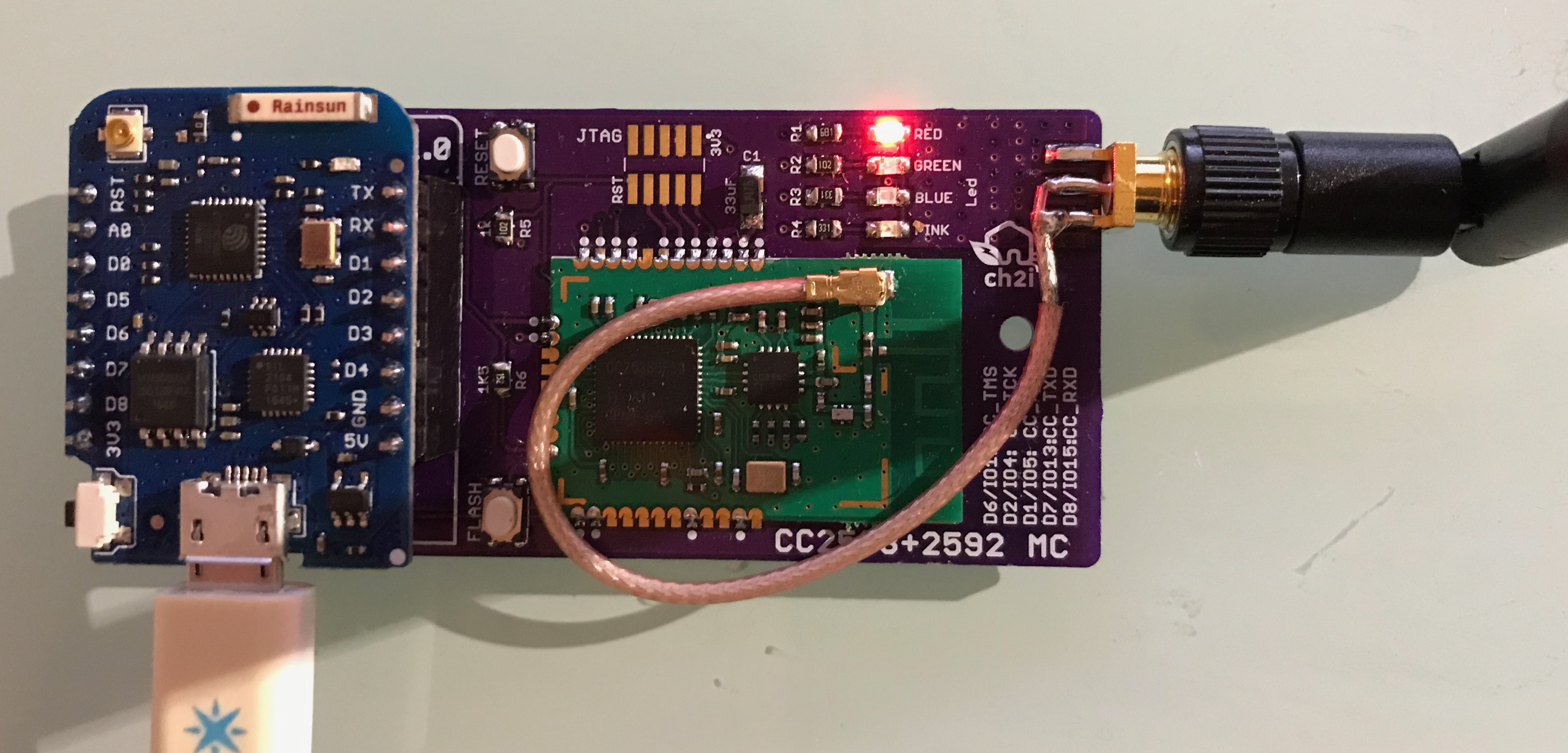


Check the dedicated github repo for detailed information
H4NC~
User h4nc created a custom PCB to connect a NodeMCU and a CC2530 board.
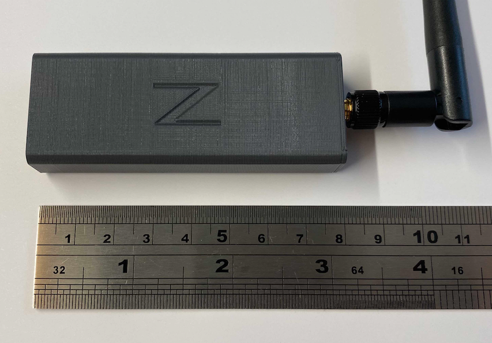
You can also get a complete Z2T module with case, pre-flashed and ready to configure and deploy.

Configuration~
Flash Zigbee Adapter~
Zigbee2Tasmota requires a TI CC2530 based module flashed with Z-Stack CC2530 firmware file from Koen Kanters.
Due to memory constraints of the CC2530, you can only pair 16 devices to a coordinator (See details).
Note
There is an alternative firmware allowing for Zigbee routers to create a mesh network and go beyond 16 devices. This is currently not tested nor supported by Zigbee2Tasmota. It may be added later.
Flashing options:
- Flashing with CCLoader and ESP8266 (recommended)
- Flashing with CCLib and ESP8266
- Flash with a dedicated CC Debugger and PC
Flash Tasmota~
Once the flashing process completes, you can re-use the ESP82xx and flash Tasmota with Zigbee2Tasmota enabled tasmota-zigbee.bin binary. Otherwise, you can use any ESP82xx device.
Optional~
Run the ESP at 160MHz instead of 80MHz which ensures higher reliability in serial communication with CC2530.
In platformio_override.ini uncomment line 51:
board_build.f_cpu = 160000000L
If you find that your Zigbee2Tasmota operation is unstable, you may have an ESP82xx device that cannot operate reliably at the higher frequency. If you are using hardware serial (see below) and you still have unreliability, try compiling for 80MHz (reverse the options above) and flash the ESP82xx device again to see if operating at a lower frequency improves stability. Running at 80MHz will impact software serial communications so hardware serial is highly recommended if running the ESP82xx at 80MHz.
Flash the newly compiled binary using the normal flashing process.
Connect CC2530 to Tasmota~
If you are using your ESP82xx device to flash the Zigbee adapter as described in tutorials you may want to leave these connections in place in case you ever need to update Zigbee firmware. If not, any of the free GPIOs can be used.
It is recommended that hardware serial pins be used (GPIO1/GPIO3 or GPIO13[Rx]/GPIO15[Tx])
Due to ESP82xx GPIO pin constraints, GPIO15 can only be used as serial Tx.
The interface between the ESP82xx Wi-Fi device and the Zigbee module uses high speed serial.
Tip
Tasmota also provides serial communications emulation through software (i.e., software serial). This allows any GPIO to be used. TasmotaSerial version 2.4.x (PR #6377) has improved the reliability of software serial making it feasible for use in this application. However, if you have an option to use hardware serial, choose that.
Z2T uses software serial by default to allow for serial logging on GPIO1/GPIO3
Use SerialLog 0 to enable hardware serial on GPIO13[Rx]/GPIO15[Tx].
Recommended wiring:
| ESP Device | Tasmota | Zigbee Module |
|---|---|---|
| GPIO13 | Zigbee RX (166) | CC_TXD (A.K.A. P0_3) |
| GPIO15 | Zigbee TX (165) | CC_RXD (A.K.A. P0_2) |
| 3V3 | VCC | |
| GND | GND |
Tasmota Settings~
In the Configuration -> Configure Module page assign:
- GPIO13 to
Zigbee RX - GPIO15 to
Zigbee TX
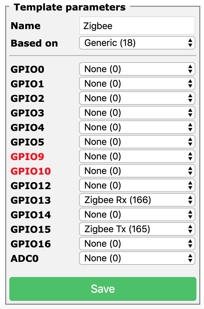
You can quickly configure Tasmota using a custom template instead.
Use this one for the recommended wiring scheme:
{"NAME":"Zigbee","GPIO":[0,0,0,0,0,0,0,0,0,166,0,165,0],"FLAG":0,"BASE":18}
First Run~
When the Tasmota device boots, Zigbee2Tasmota will wait for 15 seconds before initializing the CC2530. This time allows for Wi-Fi and MQTT to connect (hopefully).
First boot:
MQT: tele/%topic%/RESULT = {"ZbState":{"Status":1,"Message":"CC2530 booted","RestartReason":"Watchdog","MajorRel":2,"MinorRel":6}}
MQT: tele/%topic%/RESULT = {"ZbState":{"Status":50,"MajorRel":2,"MinorRel":6,"MaintRel":3,"Revision":20190608}}
MQT: tele/%topic%/RESULT = {"ZbState":{"Status":2,"Message":"Resetting configuration"}}
MQT: tele/%topic%/RESULT = {"ZbState":{"Status":3,"Message":"Configured, starting coordinator"}}
MQT: tele/%topic%/RESULT = {"ZbState":{"Status":51,"IEEEAddr":"0x00124B00199DF06F","ShortAddr":"0x0000","DeviceType":7,"DeviceState":9,"NumAssocDevices":0}}
MQT: tele/tasmota/Zigbee_home/RESULT = {"ZbState":{"Status":0,"Message":"Started"}}
ZIG: Zigbee started
ZIG: No zigbee devices data in Flash
Zigbee will automatically boot the CC2530 device, configure the device and wait for Zigbee messages.
Normal boot looks like:
MQT: tele/%topic%/RESULT = {"ZbState":{"Status":1,"Message":"CC2530 booted","RestartReason":"Watchdog","MajorRel":2,"MinorRel":6}}
MQT: tele/%topic%/RESULT = {"ZbState":{"Status":50,"MajorRel":2,"MinorRel":6,"MaintRel":3,"Revision":20190608}}
MQT: tele/%topic%/RESULT = {"ZbState":{"Status":3,"Message":"Configured, starting coordinator"}}
MQT: tele/%topic%/RESULT = {"ZbState":{"Status":51,"IEEEAddr":"0x00124B00199DF06F","ShortAddr":"0x0000","DeviceType":7,"DeviceState":9,"NumAssocDevices":0}}
MQT: tele/%topic%/RESULT = {"ZbState":{"Status":0,"Message":"Started"}}
ZIG: Zigbee started
ZIG: Zigbee devices data in Flash (516 bytes)
You can force a factory reset of your CC2530 with ZigbeeReset 1 and reboot