DS18x20 temperature sensor~
This feature is included in tasmota, tasmota32, tasmota-knx, tasmota-display and tasmota32-bluetooth binaries
When compiling your build add the following to user_config_override.h:
#ifndef USE_DS18x20
#define USE_DS18x20               // Add support for DS18x20 sensors with id sort, single scan and read retry (+2k6 code)
//  #define W1_PARASITE_POWER     // Optimize for parasite powered sensors
#endif
DS18x20 driver supports DS18B20, DS18S20, DS1822 and MAX31850 1-Wire digital temperature sensors.
Configuration~
Wiring~
| DS18b20 | ESP |
|---|---|
| 1 GND | GND |
| 2 Data | GPIOx |
| 3 VCC | 3.3v |
Warning: DS18x20 will not work on GPIO16
You need to connect a 4.7K pullup resistor from data to 3.3V.

Tasmota Settings~
In the Configuration -> Configure Module page assign:
GPIOx to DS18x20
After a reboot the driver will display Temperature.
Shelly 1 Temperature Addon~
Shelly dual pin mode is supported by an additional pin assignment:
- GPIOy to
DS18x20-o
Commands~
SetOption74 may be used to enable/disable internal pullup when using a single DS18x20 sensor (for multiple sensors, you have to use an external pullup resistor).
SetOption126 Enable arithmetic mean over teleperiod for JSON temperature for DS18x20 sensors.
TempRes Temperature sensor resolution: 0..3 = maximum number of decimal places.
TempOffset can be used to add/sub an offset to the measured temperature. This setting affects all temperature sensors on the device.
Multiple Sensors~
Tasmota supports multiple DS18x20 sensors connected to a single ESP8266/ESP32 chip using a single or multiple (up to 4) GPIOs. The default maximum is set to 8 sensors (driver code). It is possible to override this number in user_config_override.h by adding a line with #define DS18X20_MAX_SENSORS <new-value> (ESP8266/ESP32 only). However one should take into account that:
- Display on the console is limited and SENSOR log will be truncated above 11 DS18x20.
- MQTT buffer length is limited and SENSOR message will be truncated above 18 DS18x20.
- Even less if other sensors are attached to the ESP device and present in the SENSOR message.
- 1-wire has been designed to be a board-bus, not to run through long distances across a whole house. At minimum, use a shielded cable.
Note
If you increase the value above default, you are on your own. No support will be provided.

Every sensors will get a unique ID used in webUI and MQTT telemetry.
{"Time":"2021-01-02T09:09:44","DS18B20-1":{"Id":"00000566CC39","Temperature":13.3},"DS18B20-2":{"Id":"0000059352D4","Temperature":1.2},"DS18B20-3":{"Id":"000005937C90","Temperature":22.5},"TempUnit":"C"}
Sensor Aliases~
By default, sensors are named using the <sensor model>-<n> scheme (e.g. DS18B20-1), where the number is practically random (based on the sensor's address). This means when you add or remove a sensor, the numbers of the sensors may change.
To assign a static alias to a certain ID, you can use DS18Alias command. This must be enabled by setting #define DS18x20_USE_ID_ALIAS in user_config_override.h and then compile your own binary.
To display the full IDs of all connected sensors, run the command DS18Alias without any parameters.
To set a static index, use the DS18Alias <sensor ID>,<n> command. For example DS18Alias 113C01F096174528,2. This will rename the sensor to the scheme DS18Sens-<n> and it leads to the following output of the command DS18Alias:
{"DS18Sens-2":{"Id":"113C01F096174528"},"DS18Sens-1":{"Id":"783C01F096F2BB28"},"DS18Sens-3":{"Id":"8B0316C310F3FF28"}}
When you set <n> to an alphanumeric value (not starting with a number), the whole name is replaced with the given value. E.g. DS18Alias 113C01F096174528,Outdoor
As this settings are not persistent across reboots, you should add a System#Boot rule (or an entry in autoexec.bat). This will set your aliases again after each boot. For example:
Rule1 ON System#Boot DO
Backlog DS18Alias 783C01F096F2BB28,1;
DS18Alias 113C01F096174528,2;
DS18Alias 8B0316C310F3FF28,3
ENDON
To remove the alias and return to the default naming scheme, use 0 as the number index: DS18Alias <sensor ID>,0
For example: DS18Alias 113C01F096174528,0
Compile Options~
There are some compile options (driver code):
USE_DS18x20_RECONFIGURE: When sensor is lost keep retrying or re-configure
DS18x20_USE_ID_AS_NAME: Use last 3 bytes for naming of sensors
DS18x20_USE_ID_ALIAS: Enable DS18Alias command (see above)
Sensor Versions~

Pinout when looking at the flat side of the TO-92 package sensor: GND, Signal, VDD. Pinout of the wired sensor: black: GND; yellow or white: Signal, red: VDD
THR316D/THR320D Wiring Notes~
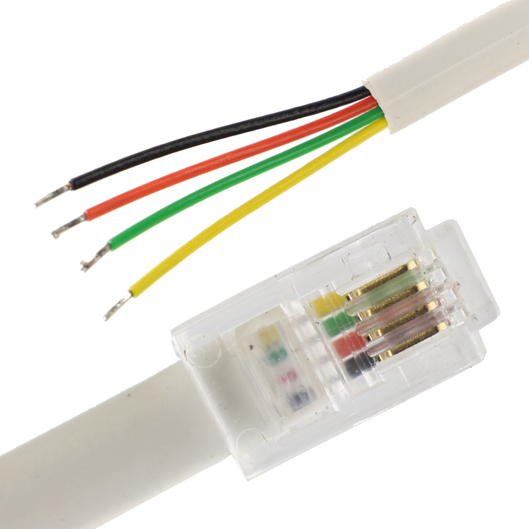
| 4P4C RJ9/RJ10/RJ22 | ESP | DS18b20 |
|---|---|---|
| 1 (Yellow on image) | 3V3 GPIO27 providing 3V3 | Red on wired sensor |
| 2 (Green on image) | GPIO25 data | Yellow or White on wired sensor |
| 3 (Red on image) | NC | |
| 4 (Black on image) | GND | Black on wired sensor |
You do not need to add a pull-up resistor (The THR316D/THR320D has it built in.)
ESP-01 Wiring Notes~
Danger
BEWARE OF MANY VISUALLY SIMILAR BOARDS TO THIS RELAY BOARD but different schematics
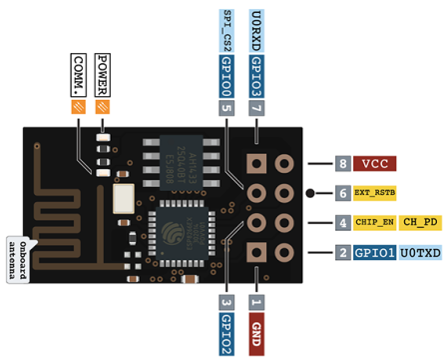
Some modules have culprits: * "CH_PD" is not set to HI (3.3V) as actually required. Usually this is done with a 10K resistor or directly to 3.3V, I have connected directly to the 3.3V * A resistor (R2 10k) which is connected between the terminal GPIO0 to ground. This ensures that the GPIO0 is always pulled to ground, which actually places the ESP-01 in program mode (flashing). To make the module working it is necessary to remove (solder out).
Connect DS18B20 to the GPIO2 (see diagram below - soldering not necessary, it is possible to put the wires and the resistor directly in to the female part of the connector together with ESP 01S module pins)
After flashing, set up Tasmota (see images below): * "Generic module" * GPIO0 as Relay 1 * GPIO2 as DS18x20
Rule Triggers~
The following trigger events are supported for use in Rules:
Single sensor attached:
ON DS1820#Temperature DO <command> ENDON
  ON DS1820_1#Temperature DO <command> ENDON
  ON DS1820_2#Temperature DO <command> ENDON
  ON DS1820_3#Temperature DO <command> ENDON
  ON DS1820_..#Temperature DO <command> ENDON
ON DS1820_1#Temperature!=%Var1% DO backlog publish espTempertature/sensor/DS1820_1/data %value%; Var1 %value% ENDON