ESP32~
ESP32-S2/S3 support is in beta and not all functions or supported peripherals will work reliably.
Due to the scope and activity of development there might be breaking changes and incompatibilities between major and minor versions of Tasmota32. In case of problems first erase flash and serial flash the latest development binary.
ESP32 Differences~
All ESP32 systems on a chip (SoC) are 32-bit MCUs with 2.4 GHz Wi-Fi & Bluetooth/Bluetooth LE built in. There are distinct product lines which differ from each other in varying degrees. See ESP32 modules list for the full list.
ESP32~
An ESP32 has two or one Xtensa® 32-bit LX6 microprocessor(s) with clock frequency ranging from 80 MHz to 240 MHz. Tasmota32 is initially developed and tested with the dual core ESP32-D0WD-V3 and later expanded to include single core or PSRAM versions. Only first 4MB of PSRAM are useable (and reported) even if a bigger chip is connected (see here for more information).
Single core SoCs do not work with standard binaries, for those use only tasmota32solo1.bin or compile your own binary using the tasmota32solo1 environment.
ESP32-S2~
A more cost-efficient version of ESP32, cut down to a single core and several dedicated hardware security features (eFuse, flash encryption, secure boot, signature verification, integrated AES, SHA and RSA algorithms). It has 43 available GPIOs. Product page for ESP32-S2
Use tasmota32s2- binaries for this line of chips.
ESP32-S3~
Keeping the security improvements the S3 line now again features the dual core SoC with Bluetooth upgraded to V5 . Product page for ESP32-S3.
Use tasmota32s3- binaries for this line of chips.
ESP32-C3~
Unlike previous versions, C3 is a single-core Wi-Fi and Bluetooth 5 (LE) microcontroller SoC based on the open-source RISC-V architecture. It is available as ESP32-C3-MINI-1 and ESP32-C3-WROOM-02 modules. Product page for ESP32-C3
Use tasmota32c3- binaries for this line of chips.
ESP32-C6~
The ESP32-C6 series is based on the RISC-V architecture and offers both Wi-Fi and Bluetooth (LE) support. Product page for ESP32-C6
Use tasmota32c6- binaries for this line of chips.
ESP32-P4~
The ESP32-P4 series is designed for high-performance applications and features a dual-core RISC-V processor, extensive peripheral support and advanced security features. It is particularly suitable for demanding control and multimedia applications, although support in Tasmota is just beginning and many new features are not implemented yet. Product page for ESP32-P4
Use tasmota32p4- binaries for this line of chips.
Flashing~
Use Tasmota Web Installer to easily flash ESP32 devices.
Other options include:
ESP_Flasher for flashing an ESP32 or ESP82xx (Windows, MacOs or Linux (Ubuntu)).
esptool.py - use the following command syntax:
esptool.py write_flash 0x0 tasmota32.factory.bin
Use a proper power supply!
ESP32 is power hungry and there's a high chance it will not be able to boot properly off the serial-to-USB power. Power it from a separate power supply that can provide at least 500mA.
You can download precompiled binaries:
- development branch from http://ota.tasmota.com/tasmota32/
- stable releases from http://ota.tasmota.com/tasmota32/release/
OTA upgrade from older versions of tasmota32 might fail due to significant changes in partition tables.
Exclusive Features~
Autoconf~
As devices get more complex, it was useful to find a simpler way for users to configure a device in one click, including Template information, Ethernet configuration, SetOptions and Berry drivers.
After flashing Tasmota, open the web UI of the device and navigate to Configuration -> Auto-configuration. Select your device from the drop-down and click Apply Configuration.
Configuration files are stored here: https://github.com/tasmota/autoconf
To use it you need to have #define USE_AUTOCONF.
Berry Scripting~
ESP32 introduces Berry language as a more approachable scripting language. Berry is very powerful and you can even code an I2C driver using it.
LVGL~
Use LVGL in conjunction with Berry on devices with displays and touch displays to design your own UI.
CPU Temperature Sensor~
Tasmota will create an internal temperature sensor and display the values in the webUI and MQTT. The accuracy of this sensor varies a lot depending on the ESP32 chip involved and should not be taken as a reliable metric.
Enable display of ESP32 internal temperature with SetOption146 1
{"Time":"2021-01-01T00:00:00","ESP32":{"Temperature":41.7},"TempUnit":"C"}
SetSensor127 0 ADC~
Despite ESP32 has 18 ADC input pins, they are grouped in two channels: ADC1 (gpios 32, 33, 34, 35, 36, 37, 38, 39) and ADC2 (gpios 0, 2, 4, 12, 13, 14, 15, 25, 26, 27). ADC2 channel doesn't work with Wifi activated, so Tasmota can only use ADC1 channel. Besides, ESP32 boards usually have only 6 pins available: 32, 33, 34, 35, 36 and 39.
DAC~
DAC GPIOs are supported through Berry gpio module.
Hall Sensor~
ESP32 has a built in hall effect sensor that detects changes in the magnetic field in its surroundings. It is located behind the metal lid of the module and connected to GPIO36 and GPIO39.
To enable set in module configuration or template:
- GPIO36 as
HallEffect 1 - GPIO39 as
HallEffect 2
I2S~
ESP32 contains two I2S peripherals. These peripherals can be configured to input and output sample data via the I2S driver. Read more...
I2S is possible through I2S Audio or Berry gpio module.
Touch Pins~
ESP32 has 10 capacitive touch GPIOs. More on configuring and using them....
Compiling~
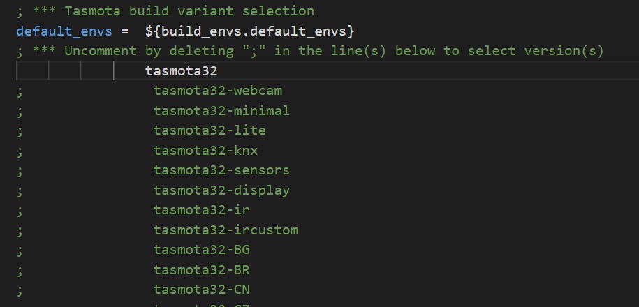
Uncomment the tasmota32xxx build you want to compile in platformio_override.ini. For example, uncommenting tasmota32 will build tasmota32.bin on the next Build task in Platformio.
All binaries use user_config_override.h if it exists.
Working Devices~
Tasmota Supported Devices Repository has a more extenstive list of ESP32 based devices.