You can wire peripherals (sensors, displays, switches, LED lights, ...) to available pins of the ESP8266 chip that controls these devices.
To make a link between the different naming schemes the Pin Definition overview in the ESP8266 wiki is quite helpful.
Examples~
Connect switch~
If you take a Sonoff Basic and connect a switch between pin4 (GND) and pin5 (GPIO14) of the 5 pin programming header you now have a second switch connected to the device. You can set this through the module config page as option Switch1 (9) or from the command line with gpio14 9.
See Buttons and Switches for more information.
Connect jack~
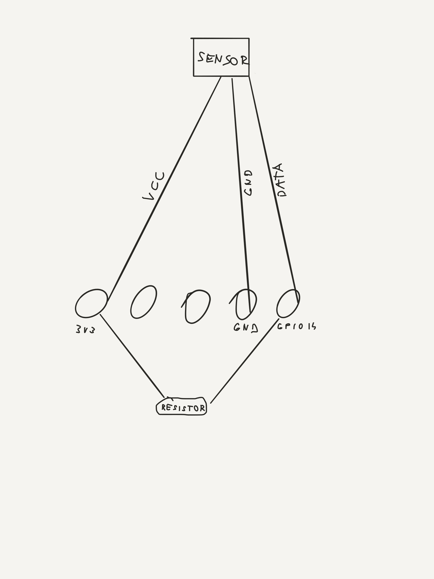
Instead of connecting a switch, you could connect a 4-pin 2.5mm jack, with the pins wired:
| Jack | Pin | ESP8266 |
|---|---|---|
| tip | 5 | GPIO14 |
| R1 | no connection | |
| R2 | 1 | GND |
| R3 | 4 | 3.3V |
You can then plug a sensor into the jack like you would to a Sonoff TH and define what sensor you have connected to GPIO14.
Restrictions~
Danger
If you can avoid it, don't use GPIOs: 0, 1, 2, 6-11, 15 and 16. That leaves 4, 5, 12, 13, 14 as GPIOs without any constraints. 3 being RX is also good to avoid (PWM is not working on this GPIO).
Others can be used but you have to mind the constraints outlined in this document.
Voltage and Current~
Danger
The ESP8266 is a 3.3V microcontroller, so its I/O operates at 3.3V as well. The pins are not 5V tolerant, applying more than 3.6V on any pin will release the magic smoke (fry the chip).
The maximum current that can be drawn from a single GPIO pin is 12mA.
Power Supply~
Danger
The power supplied to the device is one of the most important elements for stable device operation. Many devices on the market have barely adequate power supplies for normal operation. Connected peripherals may strain the ability of the power supply on the device to deliver appropriate power to all the components, both on-board as well as externally connected.
Voltage regulation issues typically result in fatal exception fault code 1. You must ensure that the device receives sufficient power (current and appropriate voltage level). Take into account the current that each wired component (e.g., sensor) will draw from the device itself.
Electrical Considerations~
When you switch a GPIO pin to an input and hang a long wire off of it, that wire can pick up stray signals and cause the voltage on the GPIO pin to vary. This can cause the system to think the switch has changed.
To fix this, there are several things you can do.
- add a pull-up resistor
- add a bypass capacitor
- shielding on the wire
- use twisted pair wiring
A pull-up resistor is a resistor connected between the GPIO pin and 3.3v. The exact value of this is not critical, 4.7k is a common value to use, as is 10k. This ensures that when the switch it open, the GPIO pin will go high.
A bypass capacitor is a small (pF range) capacitor that is connected between the GPIO and ground. This provides a path for any radio signals that are picked up by the wire to go to ground and not confuse the system.
Shielding or using twisted pair wiring are other ways to reduce the effect of radio signals on the system.
Example for 10K Resistor (issue#2708)
The ESP8266 Hardware~
Complete document available from https://tttapa.github.io/ESP8266/Chap04%20-%20Microcontroller.html
Digital I/O~
Just like a normal Arduino, the ESP8266 has digital input/output pins (I/O or GPIO, General Purpose Input/Output pins). As the name implies, they can be used as digital inputs to read a digital voltage, or as digital outputs to output either 0V (sink current) or 3.3V (source current).
Usable pins~
The ESP8266 and ESP8255 have 17 GPIO pins (0-16) but several are reserved or have constraints. Do not use any of the reserved pins. If you do, you might crash your program. On the ESP8266, six pins (GPIO 6 - 11) are used to interface the flash memory (the small 8-legged chip usually right next to the ESP8266). The ESP8255 has its flash memory integrated into the chip which frees up GPIO 9 and 10.
GPIO 1 and 3 are used as TX and RX of the hardware Serial port (UART), so in most cases, you can’t use them as normal I/O while sending/receiving serial data.
Boot modes~
Some I/O pins have a special function during boot: They select 1 of 3 boot modes:
| GPIO15 | GPIO0 | GPIO2 | Mode |
|---|---|---|---|
| 0V | 0V | 3.3V | Uart Bootloader |
| 0V | 3.3V | 3.3V | Boot sketch (SPI flash) |
| 3.3V | x | x | SDIO mode (not used for Arduino) |
Note: you don’t have to add an external pull-up resistor to GPIO2, the internal one is enabled at boot.
We have to be sure that these conditions are met by adding external resistors, or the board manufacturer of your board has added them for you. This has some implications, however:
GPIO15 is always pulled low, so you can’t use the internal pull-up resistor. You have to keep this in mind when using GPIO15 as an input to read a switch or connect it to a device with an open-collector (or open-drain) output, like I²C. GPIO0 is pulled high during normal operation, so you can’t use it as a Hi-Z input. GPIO2 can’t be low at boot, so you can’t connect a switch to it. Internal pull-up/-down resistors GPIO 0-15 all have a built-in pull-up resistor, just like in an Arduino. GPIO16 has a built-in pull-down resistor.
PWM~
Unlike most Atmel chips (Arduino), the ESP8266 doesn’t support hardware PWM, however, software PWM is supported on all digital pins. The default PWM range is 10-bits @ 1kHz, but this can be changed (up to >14-bit@1kHz). Check Restrictions.
Analog input~
The ESP8266 has a single analog input, with an input range of 0 - 1.0V. If you supply 3.3V, for example, you will damage the chip. Some boards like the NodeMCU have an on-board resistive voltage divider, to get an easier 0 - 3.3V range. You could also just use a trimpot as a voltage divider.
The ADC (analog to digital converter) has a resolution of 10 bits.
Communication~
Serial~
The ESP8266 has two hardware UARTS (Serial ports): UART0 on pins 1 and 3 (TX0 and RX0 resp.), and UART1 on pins 2 and 8 (TX1 and RX1 resp.), however, GPIO8 is used to connect the flash chip. This means that UART1 can only transmit data.
UART0 also has hardware flow control on pins 15 and 13 (RTS0 and CTS0 resp.). These two pins can also be used as alternative TX0 and RX0 pins.
I²C~
ESP8266 doesn’t have a hardware TWI (Two Wire Interface) but it is implemented in software. This means that you can use pretty much any two digital pins. By default, the I²C library uses pin 4 as SDA and pin 5 as SCL. (The data sheet specifies GPIO2 as SDA and GPIO14 as SCL.) The maximum speed is approximately 450kHz.
SPI~
The ESP8266 has one SPI connection available to the user, referred to as HSPI. It uses GPIO14 as CLK, 12 as MISO, 13 as MOSI and 15 as Slave Select (SS). It can be used in both Slave and Master mode (in software).
GPIO overview~
| NodeMCU Labelled Pin | GPIO# | Function | State | Restrictions |
|---|---|---|---|---|
| D3 | 0 | Boot mode select | 3.3V | No Hi-Z |
| D10 | 1 | TX0 | - | Not usable during Serial transmission |
| D4 | 2 | Boot mode select TX1 | 3.3V (boot only) | Don’t connect to ground at boot time Sends debug data at boot time |
| D9 | 3 | RX0 | - | Not usable during Serial transmission |
| D2 | 4 | SDA (I²C) | - | - |
| D1 | 5 | SCL (I²C) | - | - |
| x | 6 - 8 | Flash connection | x | Not usable, and not broken out |
| x | 9, 10 | Flash connection * | Only available on the ESP8285 | |
| x | 11 | Flash connection | x | Not usable, and not broken out |
| D6 | 12 | MISO (SPI) | - | - |
| D7 | 13 | MOSI (SPI) | - | - |
| D5 | 14 | SCK (SPI) | - | - |
| D8 | 15 | SS (SPI) | 0V | Pull-up resistor not usable (extern pull down resistor) |
| D0 | 16 | Wake up from sleep | - | No pull-up resistor, but pull-down instead Should be connected to RST to wake up |