I2S Audio for ESP32~
This feature is not included in precompiled binaries
Add the following to the build environment and compile your build:
build_flags                 = ${env:tasmota32_base.build_flags}
                              -DUSE_I2S_ALL
lib_extra_dirs = lib/lib_audio added to the build environment You can create smaller firmware versions with selective use of the build flags:
  #define USE_I2S ;             base flag - always needed
  #define USE_I2S_AUDIO ;       base flag - always needed
  #define USE_I2S_MIC ;         microphone support
  #define USE_SHINE ;           MP3 encoder support for microphone
  #define MP3_MIC_STREAM ;      streaming from microphone to local network
  #define USE_I2S_AUDIO_BERRY ; the I2S module for Berry
  #define USE_I2S_AAC ;         AAC decoder - needs about 75 kB flash
  #define USE_I2S_OPUS ;        OPUS codec - needs about 25 kB flash
The main difference to the older ESP8266 sound driver is the configuration of the various settings at runtime with the command i2sconfig, which uses a hidden driver file.
I2S (Inter-IC Sound) is a serial, synchronous communication protocol that is usually used for transmitting audio data between two digital audio devices.
The I2S framework of the ESP-IDF supports 3 communication modes which are standard, PDM and TDM. TDM is the most advanced mode and very uncommon in the IOT world - there is no support for it in Tasmota yet.
Support for different I2S modes varies across the ESP32 family:
| Target | Standard | PDM TX | PDM RX | TDM | ADC/DAC | LCD/Camera |
|---|---|---|---|---|---|---|
| ESP32 | I2S 0/1 | I2S 0 | I2S 0 | none | I2S 0 | I2S 0 |
| ESP32-S2 | I2S 0 | none | none | none | none | I2S 0 |
| ESP32-C3 | I2S 0 | I2S 0 | none | I2S 0 | none | none |
| ESP32-C6 | I2S 0 | I2S 0 | none | I2S 0 | none | none |
| ESP32-S3 | I2S 0/1 | I2S 0 | I2S 0 | I2S 0/1 | none | none |
Note the limited support for PDM microphones.
Audio settings~
Without any additional argument i2sconfig will print the current audio configuration to the console in JSON format, e.g.:
MQT: stat/tasmota_4359CC/RESULT =
{"I2SConfig":
{"Sys":{"Version":2,"Duplex":0,"Tx":0,"Rx":1,"Exclusive":0,
"MclkInv0":0,"MclkInv1":0,"BclkInv0":0,"BclkInv1":0,"WsInv0":0,
"WsInv1":0,"Mp3Preallocate":1},
"Tx":{"SampleRate":16000,"Gain":10,"Mode":0,"SlotMask":3,
"SlotConfig":0,"Channels":2,"APLL":1},
"Rx":{"SampleRate":32000,"Gain":30,"Mode":1,"SlotMask":1,
"SlotWidth":32,"Channels":1,"DCFilterAlpha":32511,
"LowpassAlpha":17719,"APLL":1,"WsWidth":32,"WsPol":0,"BitShift":1,
"LeftAlign":1,"BigEndian":0,"LsbOrder":0,
"DMAFrame":768,"DMADesc":5}}}
Some properties are easy to understand like number of channels or sample rate.
The "weird ones" a very likely data structures from the I2S audio framework of the ESP-IDF. Numeric values for these properties are integer representations of enums in many cases.
This allows for a very flexible audio setup to support a wide range of hardware combinations with one firmware image.
Changing values is done by passing a JSON with the new key-value-pair.
Examples:
i2sconfig {"Rx":{"Mode":0}} switch input of the microphone to standard modes, where all other default values are set to use an INMP441 with left-channel-configuration.
i2sconfig {"Rx":{"SlotMask":2}} would change the microphone in standard mode to the right channel.
i2sconfig {"Rx":{"SampleRate":48000}} changes sample rate of the microphone.
i2sconfig {"Rx":{"DMAFrame":768}} use DMA buffer for higher sample rate.
How to apply complex settings? The ugly truth ...~
In order to support basically any type of microphone in a combination with a certain ESP32 type, we need to find documentation about the needed settings (this works rarely or never) or find/generate demo code, which can be converted to Tasmotas I2S driver.
In example the INMP441 does not need the same setting on different SOC's of the ESP32 family.
For the ESP32-S3 this microphone works with the following configuration macro from Espressif (found with trial and error):
#define I2S_STD_PHILIPS_SLOT_DEFAULT_CONFIG(bits_per_sample, mono_or_stereo) { \
    .data_bit_width = bits_per_sample, \
    .slot_bit_width = I2S_SLOT_BIT_WIDTH_AUTO, \
    .slot_mode = mono_or_stereo, \
    .slot_mask = (mono_or_stereo == I2S_SLOT_MODE_MONO) ? \
                I2S_STD_SLOT_LEFT : I2S_STD_SLOT_BOTH, \
    .ws_width = bits_per_sample, \
    .ws_pol = false, \
    .bit_shift = true, \
    .msb_right = true, \
}
Now we have to translate this.
I2S_SLOT_BIT_WIDTH_AUTO is an enum with an int value of 0, so we need:
i2sconfig {"Rx":{"SlotWidth":0}}
I2S_STD_SLOT_LEFT and I2S_STD_SLOT_BOTH are enums too with values of 1 and 3. For mono:
i2sconfig {"Rx":{"SlotMask":1}}
The next values are pretty obvious:
i2sconfig {"Rx":{"WsWidth":16}}
i2sconfig {"Rx":{"WsPol":0}}
i2sconfig {"Rx":{"BitShift":1}}
The C struct member .msb_right does only exist on ESP32 and ESP32-S2 and is not part of the driver settings with this name.
Instead the settings key LsbOrder is reused for these 2 SOC's:
i2sconfig {"Rx":{"LsbOrder":1}}
The rest of the data is inferred from the currently fixed sample rate of the Tasmota driver of 16 bits and channel number with the driver key channels.
Audio Output~
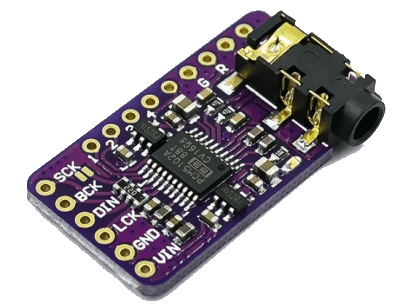
For audio output an I2S digital audio decoder (DAC) board is required. It is recommended to use an external DAC
| I2S DAC | ESP32 |
|---|---|
| BCLK | I2S_BCLK |
| LRCK/WS | I2S_WS |
| DIN | I2S_DOUT |
| SD | NC |
| GAIN | NC |
| VIN | 3V3 or 5V |
| GND | GND |
Internal DAC~
ESP32 has two 8-bit DAC (digital to analog converter) channels, connected to GPIO25 (Channel 1) and GPIO26 (Channel 2).
Those channels can be driven via the I2S driver when using the “built-in DAC mode” enabled with USE_I2S_NO_DAC
Commands~
| CMD DAC | action |
|---|---|
| I2SGain | 0..100 = sets the volume of the audio signal |
| I2SPlay | <decoder_type> file = plays an audio file from the file system, sound is played in a separate task not blocking the system |
| I2SLoop | <decoder_type> file = plays an audio file from the file system in an endless loopExample: i2sloop2 file.opus |
| I2SRtttl | string = play Ring Tones Text Transfer Language (RTTTL) ringtones (requires defined USE_I2S_RTTTL) |
| I2SSay | text = speaks the text you typed (only English language supported) |
| I2STime | tells current Tasmota time in English (requires defined USE_I2S_SAY_TIME) |
| I2SWr | <decoder_type> url = starts playing a radio stream, no blocking (requires defined USE_I2S_WEBRADIO)no parameter = stops playing the stream |
| I2SStop | stops current play operation |
| I2SPause | pauses current file play operation, can be resumed with i2splay (without any argument) |
Tasmota can support multiple audio codec types for file playback/loop, microphone recordings and web radio, which are MP3, AAC (decoder only!!) and OPUS. For the referring commands the type is provided at the index position of the command (right behind the command without a space). The filename does not matter, there is no check for naming conventions. Wrong combinations can lead to crashes.
| Codec index | Codec name |
|---|---|
| 0 | AAC - decoder only, must be provided as AAC format, not embedded in an M4A container! |
| 1 | MP3 - if you do not provide the type explicitly, this is the automatic default |
| 2 | OPUS - most modern and open standard, but has highest memory requirements. Allows nearly perfect gapless looping. |
Audio Input~
For microphone input an I2S microphone must be connected. It is pretty common, that the captured audio signal has a very low volume.
Hence a relatively high gain factor is needed, that can be configured with:
i2sconfig {"Rx":{"Gain":30}}
I2S Microphone - standard mode~
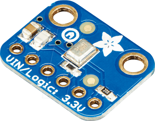
Use command i2sconfig {"Rx":{"Mode":0}} to switch audio input to standard mode.
| I2S Microphone | ESP32 |
|---|---|
| SCK | I2S_BCLK |
| WS | I2S_WS |
| SD | I2S_DIN |
| L/R | GND |
| VDD | 3.3V |
| GND | GND |
If you're using only the microphone without a DAC you still need to set pin I2S_DOUT to an unused GPIO.
I2S Microphone - PDM mode~
Pulse density modulation (PDM) microphones are handled as I2S microphones in the ESP-IDF and need only two data wires in comparison to standard I2S microphones. They're used in ESP32-S3-BOX, Seeed Xiao Sense and others.
Use command i2sconfig {"Rx":{"Mode":1}} to switch audio input to PDM mode.
| Microphone | ESP32 |
|---|---|
| CLK | I2S_WS |
| DATA | I2S_DIN |
| L/R | GND |
| VDD | 3.3V |
| GND | GND |
| NC | I2S_DOUT |
| NC | I2S_BCLK |
When using PDM microphones the microphone CLK pin is configured as I2S_WS in Tasmota.
Commands~
ESP32 with enough RAM required! PSRAM recommended.
Optional: i2sconfig {"Sys":{"Mp3Preallocate":1}} to turn on buffer preallocation at boot time. Can solve issues, if there is not enough contiguous RAM available later.
| CMD | Action |
|---|---|
| I2SMIC | Internal debug function. Can be used to do a silent warm start of the microphone to avoid the initial noise, that basically every I2S microphone produces. |
| I2SRec | <encoder_type> file = starts recording a .mp3 or .webm audio file to the file system, no blocking,correct file suffix provided by the user, no parameter = stops recording -? = shows how many seconds already recorded |
| I2SStream | (requires defined MP3_MIC_STREAM)1 = starts streaming .mp3/.webm server at http://<device_ip>:81/stream.mp3 or http://<device_ip>:81/stream.webm0 = stop the stream |
Supported sampling frequencies are:
32000, 44100 and 48000 Hz - for MP3
8000, 12000, 16000, 24000, 48000 Hz - for Opus/Webm
Frequencies above 32000 Hz will probably bring down most ESP32's, which have to punch above their weights here, although it might work with very good WiFi conditions - especially on the ESP32-S3.
8000 Hz will distort voices quite a lot.
The efficiency of the Opus encoder reveals weaknesses of many clients (including VLC, Chrome and Firefox), which do not adapt their receive buffers to the low bandwidth of the audio stream. Thus these first fill up the buffers - holding above 5- 30 seconds now - and start playing with the resulting latency.
Notable exception is Apple's Safari with a delay of about 1 second. The cross-platform console player mpv is not far behind.
Streaming can introduce rhythmic noise into the stream with the send rate of the data packets by interference of the WiFi radio. Proper cabeling and shielding is needed here. This can be quite difficult to achieve.
I2S Audio Bridge~
Starts a UDP audio service to connect 2 ESP32 devices as an audio intercom (an example).
Needs audio output and microphone on 2 devices (no PSRAM needed)
build_flags                 = ${env:tasmota32_base.build_flags}
                              -DUSE_I2S_ALL
                              -DUSE_I2S_BRIDGE
| CMD bridge | action |
|---|---|
| I2SBridge | ip = sets the IP of the slave device0 = stop bridge1 = start bridge in read mode2 = start bridge in write mode3 = start bridge in loopback mode4 = set bridge to master5 = set bridge to slave6 = set microphone to swapped7 = set microphone to not swappedp<x> = sets the push to talk button where x is the button's GPIO pin number |
If a push to talk button is defined the bridge goes to write mode if the button is pushed and to read mode if the button is released.
Codec / DAC~
Some ESP boards contain integrated circuits or modules that convert audio signals between analog and digital forms, sometimes with support for digital audio processing, mixing and volume control. These external audio codec chips are typically controlled via an additional I2C connection, while the pure audio data still runs over I2S.
The intended integration into the core I2S audio driver works with an additional Berry driver that establishes the I2C connection and may provide additional audio commands, while communicating with the core I2S driver via some callbacks.
A way to ease the setup work for the end user is to create Autoconf packages for specific boards. Examples already exist for the audio boards Louder-ESP32 and Louder-ESP32S3 (each using a TAS5805m), which, after initial WiFi setup, only have to be selected in the Autoconf section of the Configuration menu.
Currently there is no official support for any of these devices, but you may suggest a board to be looked at in Tasmota's GH discussions or in the Discord channel.