Lights
You know what lights do.... Right? 💡
Control Lights~
with WebUI~
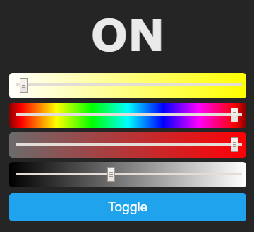
Tasmota webUI displays Brightness, CT, White, Color Picker, Color Saturation or PWM Level sliders depending on the light component, the number of PWM channels configured and SetOptions used.

Tasmota uses a HSB color model, which besides other more subtile differences compared to HSL means, that the color must be desaturated to reach complete black or white.
| Control | Range | Commands and details |
|---|---|---|
| Brightness | 0..100 (percent) | Dimmer, HSBColor3: Brightness of the light |
| Hue | 0..359 (degrees) | HSBColor1: Color as an angle in the color wheel |
| Sat | 0..100 (percent) | HSBColor2: saturation of the color, 0=grey/white, 100=pure color |
| CT | 153..500 (mireds) | CT: white color temperature, from 153 (Cold White) to 500(Warm White) |
with Commands~
See light commands for how to control lights.
Light Types~
Switched Lights aka Relays~

Switched or On/Off lights are controlled through Relay GPIOs.
If you define multiple relays, they are controlled with Power<x> starting at x=1.
Alexa: You can use Wemo emulation, your device will appear as a switch. You can change it to a light in the Alexa app.
Alexa: If you have one or multiple relays, you can use Philips Hue emulation. All devices will appear as On/Off lights, and named accordingly to FriendlyName. Note: If you have only Echo Spot 2nd generation, your light will have a dummy dimmer.
| Configuration | (see below) |
|---|---|
| Commands | Power |
| Configuration | none |
1 Channel - Dimmable Light~

1 channel lights are often white lights with On/Off controls and dimmer.
Alexa: You can use Philips Hue emulation, the light will appear as white light with dimmer.
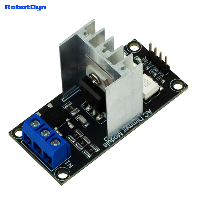
Leading edge dimmer: You can also configure a leading edge dimmer on 230V with the 1 channel configuration. In this case you need a TRIAC and a zero-cross detection that give a pulse with every crossing of the 0V of the sinus curve. The dimmer is power callibrated. 10% --> 10% light or power consumption on a device like a heater. The Dimmer is e.g. suitable to dynamically pump remaining solar power into a heat sink.
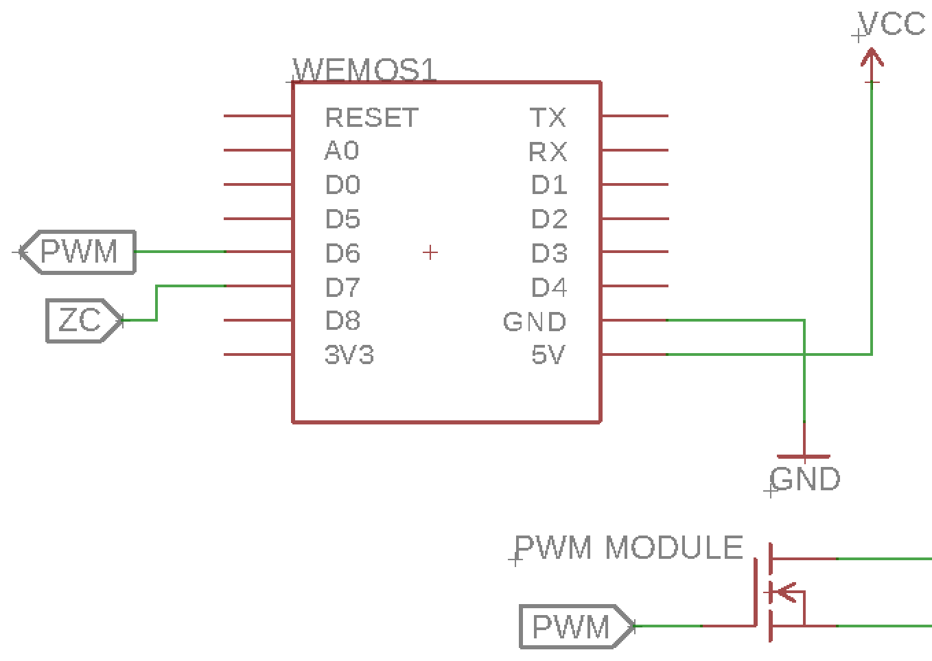
Robotdyn AC dimmer configuration
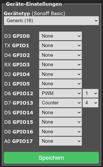
Connect zero-crossing to GPIO of Counter4. Define a PWM and connect
| Configuration | (see below) |
|---|---|
| Dimmer,Channel1 | PWM1 |
| Channel2 | PWM2 (optional) |
| Channel3 | PWM3 (optional) |
| Channelxx | PWMxx (optional) |
| Zero-Cross PIN | COUNTER4 (mandatory) |
| Commands | ZCDimmerSet |
Example schematic:
Example config:
Preferably before connecting the ZC & PWM perform the following commands:
SetOption99 1-> to enable detection of the raising edge of the zero-crossingSetOption68 1-> with more than ONE PWM this will all operate as single lights. Control with [channelx 1..100]LedTable 0-> for normal lamps or motors. Recommendedsavedata 0-> Saving the current status create small flickering. OFF prevent this. On ESP32 recommended. Do not change after reboot!
| Configuration | (see below) |
|---|---|
| Commands | Power, Dimmer, Channel, Fade, Speed |
| Options | Auto Power On, Independant PWM Channels, Gamma Correction |
2 Channels - CCT Light~

2 channels lights are white lights with correlated color temperature (CCT) controls from Cold White (CT=153) to Warm White (CT=500).
Alexa: You can use Philips Hue emulation, the light will appear as white light with color temperature. Control through the Alexa app is limited to the CT range 199..383.
| Configuration | (see below) |
|---|---|
| Commands | Power, Dimmer, Color, White, CT |
| Options | Auto Power On, Independant PWM Channels, Gamma Correction, PWM CT |
3 Channels - RGB Lights~

3 channel lights are RGB color lights. You can set color either via RGB or HSB (not HSL). Alexa support also allows XY color, but that is not supported through commands.
Alexa: You can use Philips Hue emulation, the light will appear as Color light.
| Configuration | (see below) |
|---|---|
| Commands | Power, Dimmer, Color, HSBColor |
| Options | Auto Power On, PWM Channel Configuration, Gamma Correction, Channel Remapping |
4 Channels - RGBW Lights~


4 channel lights are RGBW, i.e. RGB light and an additional White light. White can be either Warm White or Cold White depending on the manufacturer.
Alexa: You can use Philips Hue emulation, the light will appear as Color light and White light with CT control. The CT control is only present to force pure white instead of RGB white. Changing CT will have no effect.
There is no White only slider in the UI for 4 channel lights
Use White commands or set up White Blend Mode or RGB and White Split.
| Configuration | (see below) |
|---|---|
| Commands | Power, Dimmer, Color, HSBColor, White |
| Options | Auto Power On, PWM Channel Configuration, Gamma Correction, Channel Remapping, White Blend Mode, RGB and White Split |
Danger
Some lights have limited power supply that do not allow all channels to be at full power at the same time. Be careful not to burn out your light if you force all channels to be on using Color or RGB and White Split.
5 Channels - RGBCCT Lights~


5 channel lights are RGBCCT - a 3 channel RGB light and an additional 2 channel CCT light.
Alexa: You can use Philips Hue emulation, the light will appear as Color light and White light with CT control.
| Configuration | (see below) |
|---|---|
| Commands | Power, Dimmer, Color, HSBColor, White, CT |
| Options | Auto Power On, PWM Channel Configuration, Gamma Correction, Channel Remapping, White Blend Mode, RGB and White Split |
Danger
Some lights have limited power supply that do not allow all channels to be at full power at the same time. Be careful not to burn out your light if you force all channels via Color or RGB and White Split
Independent PWM Channels~

Any combination of Relays and PWMs, when enabling SetOption68 1. Splits off the light into individually controlled Channels (Useful when connecting multiple 1 channel strips to a single controller)
| Configuration | (see below) |
|---|---|
| Commands | Power, Channel, Color |
| Options | Auto Power On, PWM Channel Configuration, Gamma Correction |
Light Options~
Gamma Correction~
Gamma Correction is enabled by default in Tasmota (LedTable 1).

Human eye perception of brightness is non linear, bringing back linearity needs a trick called Gamma Correction.
Some lights have hardware gamma correction (e.g., Sonoff B1). In that case, software gamma correction should be disabled with LedTable 0.
The curve used: orange=ideal, blue=tasmota.
How do I know if I have hardware gamma correction?
If you find your light very dark even with Dimmer 40, it can mean either you have hardware PWM, disable it with LedTable 0, or you need to apply a minimum PWM value, use DimmerRange 40,100 (adapt to the best value).
Internally Tasmota uses 10 bits resolution PWM to get smoother levels at low brightness.
When using Fade mode, a different Gamma curve (called gamma_fast). This cruve cheats slightly and makes lights increase brighness faster then normal; otherwise the light starts glowing very slowly and gives the impression that the light is not responsive.
White Blend Mode~
White Blend Mode mixes in the white channel with RGB colors while controlling the RGB light which results in a better and brighter color output. It is used only with 4 channel (RGBW) and 5 channel (RGBCCT) lights.
Enable it with SetOption105 1.
For Tasmota versions before 8.5 use command RGBWWTable 255,255,255,0 instead.
Calibration (optional)~
Generally white LEDs are brighter than RGB LEDs. If you want to keep the same brightness, you need to calibrate the white level. In this mode, any white component will be removed from RGB LEDs and sent to the white LEDs. This makes whites look much better.
Example
Color 30508000 will be converted to Color 0020503000 (0x30 is subtracted from RGB channels and added to the White channel)
To calibrate a RGBW light:
Color FFFFFF00RGBWWTable 255,255,255,255,255- reset to RGB modeRGBWWTable 255,255,255,<n>,0- (begin the calibration process with<n>== 150)- If too bright, decrease
<n>. If too dim, increase<n> - Go back to step 2 and iterate until satisfied with the color intensities.
Calibration examples for specific devices:
Sonoff B1: RGBWWTable 255,255,255,35,0 Teckin SB50: RGBWWTable 255,255,255,80,0
RGB and White Split~
By default RGBW and RGBCCT lights can only be controlled in single mode, either RGB or White (e.g., Turning on CT lights turns off RGB lights and vice versa).
Use SetOption37 128 to split RGB and White into 2 independent lights. If you are already using Channel Remapping, just add 128 to the value of SetOption37.
Channel Remapping~
Disable Auto Power On~
Lights are always powered on when a light command or a webUI slider is used and automatically powered off when color is set to black or Dimmer is set to 0.
When enabling SetOption20 1 any change to webUI sliders or using commands CT, Dimmer, HSBColor3, Color or Channel will not automatically power on the light if it is off.
PWM CT~
Module 48 or SetOption92 1
Some CCT lights use PWM1 for brightness and PWM2 for color temperature (instead of PWM1 for Cold White and PWM2 for Warm White).
For these lights, use Module 48 aka Philips Xiaomi mode, or SetOption92 1 (supported since v.8.2.0.5)
Virtual CT~
this feature is experimental and will probably not give brilliant results
Used with 4 channel RGBW lights to simulate the missing white channel (cold or warm) using RGB channels.
Enable Virtual CT with SetOption106 1 then choose which type of white you're simulating with SetOption107 where 0 is warm white and 1 is cold white
Light Categories~
Lights come in various shapes (bulb, strips, ceiling lights, ...) but in Tasmota they are separated in 3 categories:
Channel Controlled Lights~
PWM Lights~
Lights controlled using up to 5 channels (red, green, blue, cold white, warm white). Channels are controlled using PWM or APDM.
PWM (Pulse Width Modulation) is the most common method of controlling LED lights.
These lights are configured by assigning PWM1(i) through PWM5(i) components to their GPIOs; PWM<x>i means PWM is inverted. Depending on the number of used PWMs Tasmota will recognize the light as
| Channels | PWM1 | PWM2 | PWM3 | PWM4 | PWM5 |
|---|---|---|---|---|---|
| 1 | Brightness | ||||
| 2 | Cold White | Warm White | |||
| 3 | Red | Green | Blue | ||
| 4 | Red | Green | Blue | White | |
| 5 | Red | Green | Blue | Cold White | Warm White |
MY92xx~
MY92xx family of drivers uses Adaptive Pulse Density Modulation.
Configured in Tasmota by assigning MY92x1 DI and MY92x DCKI components to their GPIOs (some devices might have more than one MY92xx controller)
Channel mapping for such devices is dependent on the controllers but is easily remapped using SetOption37.
SM16716~
SM16716 LEDs, sometimes mislabelled as WS2801.
Configured in Tasmota by assigning SM16716 CLK, SM16716 DAT and SM16716 PWR component to their GPIOs.
Some SM16716 bulbs have BGR order and need SetOption37 54 to work properly.
PWM Dimmer Switches~
Specific module (requires a custom binary) for Martin Jerry/acenx/Tessan/NTONPOWER SD0x PWM dimmer switches. Brightness of the load for these dimmers is controlled by a PWM GPIO pin. They typically have power, up and down buttons, a power status LED, five brightness LEDs and another status LED. Read more...
Addressable LEDs~
Lights where each LED is individually controlled. In these lights it is possible to adjust each LEDs power, color and brightness, all just with the use of a single GPIO pin.
WebUI shows hue, saturation and brightness sliders and power toggle for these lights. Red and green color may be mixed up (observed for clone of Wemos RGB shield).
WS2812~
These are also commonly called Neopixel lights.
Configured in Tasmota by assigning WS2812 (7) component to its GPIO.
For wiring, see instructions for LED strip or Wemos RGB shield.
SK6812~
SK6812 RGBW LEDs are not supported in standard binaries and need custom compiled firmware. See instructions.
Status LEDs~
Status LEDs are the LEDs on the device used to display device information
Those LEDs are defined in a template or module using Led1, Led2, Led3 or Led4 (or Led1i, Led2i, Led3i or Led4i) and additionally using LedLink or LedLinki (LedLink was introduced in version 6.5.0.12). It is not recommended to assign Led<x> and Led<x>i with the same <x> number. Prior to version 6.5.0.12, Tasmota only supported up to two LED components to indicate the power state of the relay(s), and the Wi-Fi/MQTT connectivity status.
It is possible to wire in your own LED and assign it as any of the above mentioned but that's outside the scope of this article
If only one LED is configured, it serves both purposes; the link status LED and/or the LED that indicates the power state of the relay(s). If more than one LED component is defined, Led1/Led1i will act as the Wi-Fi/MQTT status LED and the next defined LED (e.g., Led2/Led2i) will act as the LED that indicates the power state of the relay(s). This is the default behavior. Configuring a GPIO as an LEDLink/LEDLinki component changes this behavior.

For example, on a Sonoff Basic the green LED is used as the link status LED. Once the device connects, the LED is used to indicate the relay's power status.
Link status LED~
Link status LED shows the network state, more specifically the Wi-Fi and MQTT connection status.
It blinks if the device is not connected to your Wi-Fi AP and MQTT broker (if MQTT is enabled). You can change this behaviour with LedState or turn it off with SetOption31.
Power status LED~
Power status LED shows the power status of relay component(s). LedMask determines which relay(s) are associated with the power status LED. This behavior can be modified with the LedState command. The LED is turned off by default when the relay is OFF and turned on when the relay switches ON.
Note
Depending on the device design, some LEDs are connected to the same GPIO as the relay. Those cannot be independently controlled since they have to follow the relay state.
If you have more than one LED wired independently and you want it to show the power state of the relay, you must assign an LedLink GPIO.
PWM LED Mode~
Using LedPwmMode you can change the LED display mode from simple on/off to a PWM controlled LED which will enable you to e.g., display a brighter LED when the relay is on and a dimmer LED when it's OFF so you can locate the switch in the dark but not have it obnoxiously bright.
LedPwmOff and LedPwmOn control the preset LED brightness in their respective states.
LedPower Command~
When you use LedPower you take over control of that particular LED and it stops being linked to its corresponding relay and being its power status LED.
Using LedLink~
LedLink / LedLinki is used to assign the link status LED. If your device does not have an LED for link status (or you want to use that LED for a different purpose), you can assign LedLink to an available free GPIO. When LedLink(i) is assigned, other LEDs are automatically linked to their corresponding relay and serve as that relay's power status LED - i.e., Led<x>(i) links to Relay<x>(i)
ESP32 Only Features~
PWM6+~
ESP32 has hardware PWM support, named ledc, for up to 16 channels depending on CPU type. You can mix lights and pure PWM channels. The first 5 PWM are reserved for lights, unless SetOption15 0. For pure PWM GPIOs, you can assign any PWM number, they don't need to be continuous. For example you can use PWM 1/2/3 for a 3-channel RGB light, and PWM 6 & PWM 10 for pure PWM at the same time.
| CPU type | PWM channels |
|---|---|
| ESP32 | 16 channels |
| ESP32-S2 | 8 channels |
| ESP32-C3 | 6 channels |
Channels are assigned to GPIOs in a first-in-first-serve way and PWM GPIOs are assigned first. If ledc channels are exhausted an error will appear in logs.
The following GPIOs use ledc PWM channels:
| GPIO type | Description |
|---|---|
PWM or PWMi | PWM 1..5 are used for lights, PWM O6..11 are general purpose PWM. |
LedPwmMode | Assigns a Led GPIO to a PWM channel |
Buzzer | If BuzzerPwm is used |
Backlight | PWM backlighting for displays |
XCLK | Used as a clock generator for webcam |
Example of PWM console output with 16 PWM assigned. By default PWM range is 0..1023.
RESULT = {"PWM":{"PWM1":410,"PWM2":286,"PWM3":286,"PWM4":0,"PWM5":0,"PWM6":0,"PWM7":0,"PWM8":0,"PWM9":0,"PWM10":0,"PWM11":0,"PWM12":0,"PWM13":0,"PWM14":0,"PWM15":0,"PWM16":0}}
Auto-phasing of PWM~
By default, phases of consecutive PWM are disaligned so that a PWM pulses starts when the pulse of the previous PWM channels ends. This helps in distributing over time all pulses and have a smoother effect on power supply.
You can revert this with SetOption134 1; all phases are synces and all pulses start at the same moment.
H-bridge~
H-bridge is an electronic circuit that switches the polarity of a voltage applied to a load. It uses 2 PWM outputs to control the current sent to each polarity.
When auto-phasing is enabled, you can use 2 consecutive PWM to drive a H-bridge siunce PWM phases don't overlap - under the condition that the sum of both PWM don't exceed 1023.
You must always ensure that the sum of both PWM channels is less or equal than 1023. Values over this threshold can damage the circuit!!!