MFRC522 RFID reader~
This feature is not included in precompiled binaries
When compiling your build add the following to user_config_override.h:
#define USE_SPI                         // Hardware SPI using GPIO12(MISO), GPIO13(MOSI) and GPIO14(CLK) in addition to two user selectable GPIOs(CS and DC)
#define USE_RC522                       // Add support for MFRC522 13.56Mhz Rfid reader (+6k code)
#define USE_RC522_DATA_FUNCTION         // Add support for reading data block content (+0k4 code)
#define USE_RC522_TYPE_INFORMATION      // Add support for showing card type (+0k4 code)
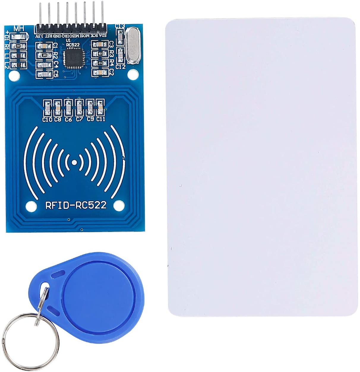
The MFRC522 is a highly integrated reader/writer IC for contactless communication at 13.56 MHz. The MFRC522 reader supports ISO/IEC 14443 A/MIFARE and NTAG. Datasheet.
This reader is ubiquitous in many Arduino starter and sensor kits. It uses SPI protocol for communication with ESP.
Wiring~
| MFRC522 | ESP8266 | Tasmota |
|---|---|---|
| SDA | GPIO0..5,15,16 | RC522 CS |
| SCK | GPIO14 | SPI CLK |
| MOSI | GPIO13 | SPI MOSI |
| MISO | GPIO12 | SPI MISO |
| IRQ | not used | |
| GND | GND | |
| RST | GPIO0..5,15,16 | RC522 Rst |
| 3V3 | 3V3 |
Warning : on esp8266, as the RST pin is pulling the signal high by default, gpio15 cannot be used for that signal. Please check esp8266 gpios specifications or the table in the section GPIO Overview
Tasmota Settings~
In the Configuration -> Configure Module page assign:
- GPIOx to
RC522 Rst - GPIOy to
RC522 CS - GPIO12 to
SPI MISO - GPIO13 to
SPI MOSI - GPIO14 to
SPI CLK
The module will reboot when you save this configuration.
During start-up the following information should be visible in your console output:
00:00:00 MFR: RC522 Rfid Reader detected
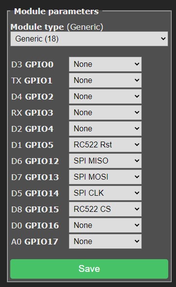
Example
Configured using NodeMCU on pins: D1 (connected to RC522 Rst) and D8 (connected to RC522 CS)
Usage~
Tasmota will scan for a new card detect 4 times per second and if found will report it via immediate telemetry.
The output on the console will look similar to the below when a new card is detected
13:10:50.346 MQT: tele/rfid-test/SENSOR = {"Time":"2021-01-23T13:10:50","RC522":{"UID":"BA839D07","Data":"","Type":"MIFARE 1KB"}}
The UID of the card/tag is reported and any text stored in BLOCK 1 of a Mifare Classic card (up to 15 characters in length) is reported in the DATA field of the JSON sent via telemetry. Please note that the DATA field cannot contain spaces.
Using the UID or DATA~
For the purpose of using card/tag data on the device itself you will need to use rules along with the events that are caused.
Example
Example rule for responding to a specific UID on the device when a card/tag matching a specific UID is presented
rule1 on RC522#UID=BA839D07 do power on endon
Breakout Boards~