NRF24L01 module~
This feature is not included in precompiled binaries
When compiling your build add the following to user_config_override.h:
#define USE_SPI            // Hardware SPI using GPIO12(MISO), GPIO13(MOSI) and GPIO14(CLK) in addition to two user selectable GPIOs(CS and DC)
#ifndef USE_NRF24
#define USE_NRF24          // Add SPI support for RF24L01(+) (+2k6 code)
#define USE_MIBLE          // BLE-bridge for some Mijia-BLE-sensors (+4k7 code)
#endif
This chip is manufactured by Nordic Semiconductors as a single chip transceiver in the 2,4 GHz band. There are many applications of this chip in many projects as a versatile very low cost wireless module.
In recent years solutions were found to use this chip for limited Bluetooth-Low-Energy communication. One of the first articles about this topic can be found here.
Subsequently, further work was done by several developers and a working bridge to read sensor data from a Xiaomi MJ_HT_V1 BLE sensor was created. The fundamental principle is, that some of these sensors send its data as a usual BLE-advertisement packet with a proprietary data format at the end of the payload. These packets had to fit into the 32 bytes of the FIFO-RX-buffer of the RF24L01, otherwise the "later" bytes were lost.
A new solution was found for the Tasmota driver.
The basic idea is to use some constant ID-bytes of the BLE-packets as the PDU-type for the NRF24l01. Thus, all bytes before these ID-bytes are lost and the size restriction for the payload is successfully circumvented. That way it is possible to read the sensor data from a Mi Flora sensor, which is positioned outside of the 32-byte-range. Of course there is still no bidirectional "real" BLE-communication, only advertisements can be read.
Configuration~
Wiring~
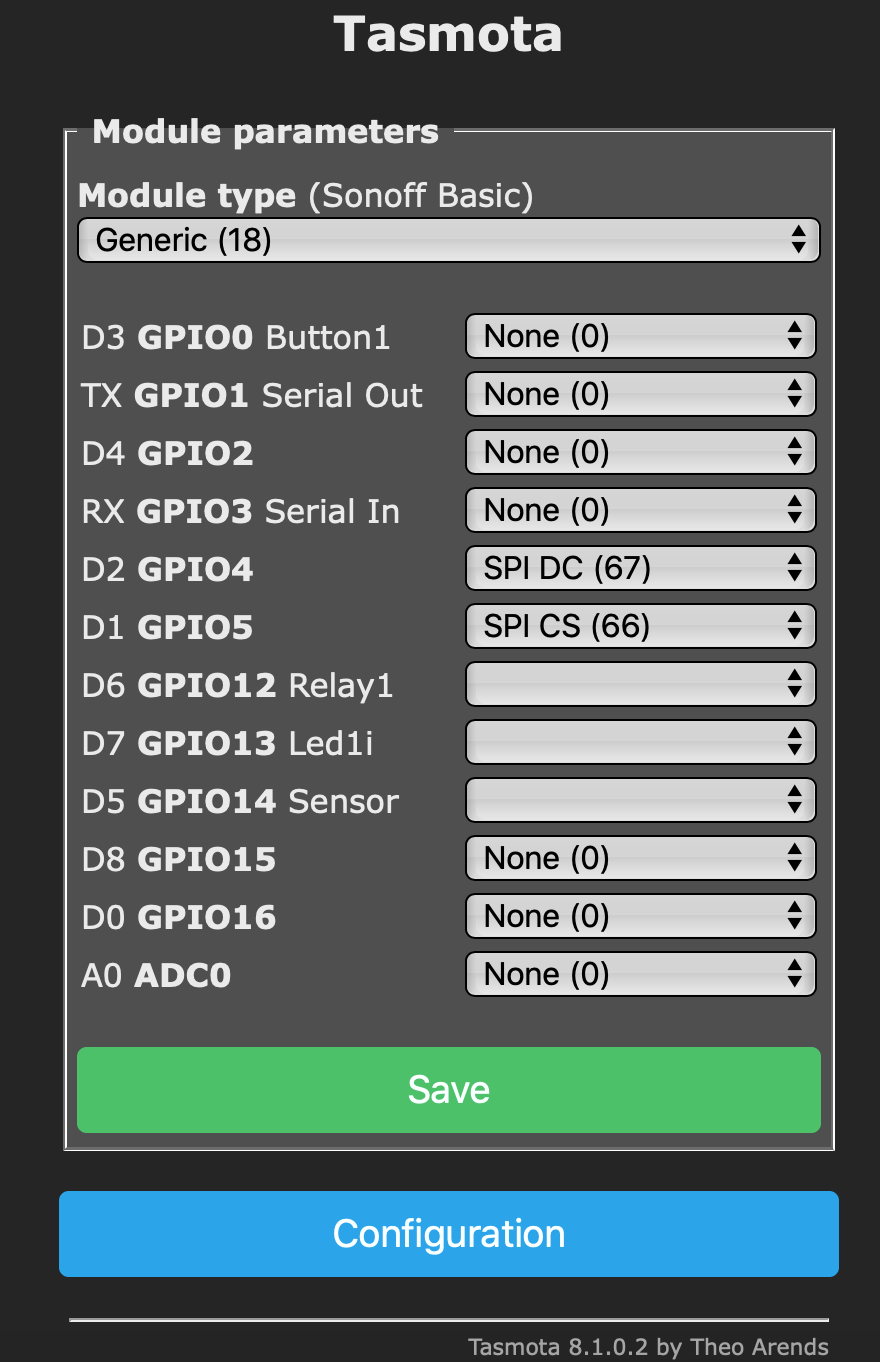
Configure the pins for SPI_DC and SPI_CS while connecting the hardware SPI pins 12 - 14 (MOSI, MISO and CLOCK).
Tip
In order to simplify the code, the pin names from the SPI-display-drivers are used in the webUI! For nRF24L01 SPI_DC translates to CSN and SPI_CS to CE.
Warning
Even slightly loose cables can lead to malfunctions of the SPI-data-transfer. This can produce a Software WDT reset.
Tasmota Settings~
No additional steps are necessary.
The initial log should like this:
00:00:00 NRF24L01 initialized
00:00:00 NRF24L01+ detected
00:00:00 MIBLE: started
The driver will do the rest automatically and start to look for known "special" packets, which will be used to extract the sensor readings. webUI and TELE-messages will be populated with sensor data. This can take a while after start and may be influenced by the general traffic on the 2,4 GHz band.
For a complete overview of supported devices, commands and features read the Bluetooth article.