Sugar Valley NeoPool Controller~
This feature is not included in precompiled binaries
When compiling your build add the following to user_config_override.h:
#ifndef USE_NEOPOOL
#define USE_NEOPOOL                       // Add support for Sugar Valley NeoPool Controller - also known under brands Hidrolife, Aquascenic, Oxilife, Bionet, Hidroniser, UVScenic, Station, Brilix, Bayrol and Hay (+6k flash, +60 mem)
#endif
Sugar Valley NeoPool are water treatment systems also known under the names Hidrolife, Aquascenic, Oxilife, Bionet, Hidroniser, UVScenic, Station, Brilix, Bayrol and Hay. It uses a RS485 interface with the Modbus data protocol for enhancement equipment like Wifi-Interface or a second attached control panel. All functions and parameters can be queried and controlled via this bus interface.
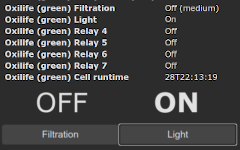
The Tasmota Sugar Valley NeoPool Controller sensor module shows the most of parameters such as the built-in display:
There are Tasmota commands implemented to control the high level functions for filtration, light and system parameters such as pH setpoint, hydrolysis level, redox setpoint etc. However, the sensor also provides low-level commands to directly read and write NeoPool register, means that you have the option to implement your own commands via home automation systems or by using the Tasmota build-in possibilities Rules with Backlog or the powerful Berry language on ESP32.
Connection~
The NeoPool controller uses a RS485 interface, the ESP has RS232 interfaces. Both are serial interfaces but with different physical specifications. Therefore to connect your NeoPool controller to an ESP82xx/32 you need a TTL-UART to RS485 converter. For an ESP8266 it is recommended to use GPIO1 and GPIO3, because the ESP then uses the serial interface of the hardware.
Using M5Stack Atom Lite with Tail485 addon~
This is the easiest and the most comfortable way to run Tasmota with the Sugar Valley system. The combination of a M5Stack Atom Lite and the Tail485 addon is very small, does not need a separate power supply (because it is powered from the Sugar Valley system) and can even be placed directly next to the system or in the junction box itself.
For this you will need:
- a M5Stack Atom Lite
- a Tail485
- a 4 wire dupont cable or 4 wire cable using a 5 pin 2,54 mm JST connector
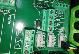
(see also Sugar Valley connection) - Sugar Valley pin 1 (+12V) goes to Tail485 pin 12V (9-24V)
- Sugar Valley pin 3 (Modbus A+) goes to Tail485 pin A
- Sugar Valley pin 4 (Modbus B-) goes to Tail485 pin B
- Sugar Valley pin 5 (Modbus GND) goes to Tail485 pin GND
For final use, put the whole thing together:
To get this combination running:
- compile your own Tasmota including the NeoPool driver as described under the red note
"This function is not included in precompiled binaries"at the very top of this page and flash your this to your M5STack Atom Lite using USB - make the configuration steps M5Stack Atom Lite with Tail485 template
- turn off the Sugar Valley device and plug the 4-wire dupont or 5 pin JST cable into the WIFI or EXTERN ports
- turn on the Sugar Valley device
That's all.
Using any other ESP~
The following TTL UART to RS485 converter have been tested with both an ESP8266 and ESP32 using a Vcc of 3.3V:
Note
Your TTL UART to RS485 converter must be able to work with an operating voltage of 3.3V. Some converters are not designed for operating with 3.3V and only works with 5V TTL level - these converters are useless. Do not operate your TTL UART to RS485 converter with 5V, your converter must be operated with the 3.3V from ESP, otherwise the ESP GPIO ports will be damaged.
Sugar Valley connection~
The Sugar Valley NeoPool RS485 connector pins are located under the connection cover, for the Sugar-Valley products on the right-hand side next to the relay connections:
The pin assignment (from top to bottom):
| Pin | Description |
|---|---|
| 1 | +12V |
| 2 | nc |
| 3 | Modbus A+ |
| 4 | Modbus B- |
| 5 | Modbus GND |
The +12V connection is the 12V from the internal power supply, do not feed in any external voltage.
You can use the "WIFI" or "EXTERN" connector, both are independent Modbus channels and uses the Modbus address 1 by default.
Note
The "DISPLAY" port can only be used if neither the built-in nor an external display is connected but since there is probably at least one display connected to one of the two "DISPLAY" ports, the "DISPLAY" port is useless.
Using WIFI Port~
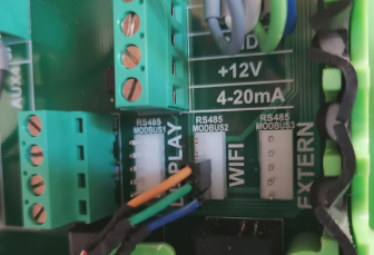
Using EXTERN Port~
Note
Leave the define for NEOPOOL_MODBUS_ADDRESS set to 1 whether you are using the "WIFI" or "EXTERNAL" port (unless you have changed the parameters for it within your Sugar Valley device).
Configuration~
Tasmota settings~
The configuration is limited to the assignment of two GPIOs under Tasmota Configuration -> Configure Module:
- change the Module type to
Generic (0)- this will restart your Tasmota - After restart set
- GPIO1 to
NeoPool RX - GPIO3 to
NeoPool TX
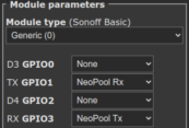
Don't be surprised that Rx seems to be connected to Tx here (and vice versa). The Rx and Tx designations are to be considered from the point of view of the respective devices, which can be confusing.
M5Stack Atom Lite with Tail485 template~
For this combination use a template, got to Console and enter the command below:
Template {"NAME":"NeoPool","GPIO":[0,0,0,0,0,0,0,0,0,0,0,0,0,0,0,1,0,1,1,1,0,0,6976,0,0,0,0,0,7008,1,0,0,0,0,0,0],"FLAG":0,"BASE":1}
This also allows the later use of the additonal GPIOs 19, 21 - 23 and 33 for other purposes (sensors or similar).
After a restart active the template using command Module 0.
Final check~
After Tasmota restarts, the main screen should display the controller data as shown above. If not, check that the A+/B pins aren't swapped and that the Rx/Tx pins are on the correct GPIOs - swap once if in doubt.
SENSOR data~
Sensor data is sent via the Tasmota topic tele/%topic%/SENSOR in JSON format every TelePeriod interval. To get the data immediately, use the Tasmota TelePeriod command without parameter:
{
  "Time": "2021-06-01T11:00:00+02:00",
  "NeoPool": {
    "Time": "2021-06-01T11:00:00",
    "Type": "Oxilife",
    "Modules": {
      "pH": 1,
      "Redox": 1,
      "Hydrolysis": 1,
      "Chlorine": 1,
      "Conductivity": 1,
      "Ionization": 1
    },
    "Temperature": 23.5,
    "Powerunit": {
      "Version": "V3.45",
      "NodeID": "XXXX XXXX XXXX XXXX XXXX 442A",
      "5V": 5.017,
      "12V": 13.904,
      "24-30V": 33.721,
      "4-20mA": 0.01
    },
    "pH": {
      "Data": 7.2,
      "Min": 7.0,
      "Max": 7.2,
      "State": 0,
      "Pump": 2,
      "FL1": 0,
      "Tank": 1
    },
    "Redox": {
      "Data": 752,
      "Setpoint": 750
    },
    "Chlorine": {
      "Data": 0.7,
      "Setpoint": 1.0
    },
    "Conductivity": 0,
    "Ionization": {
      "Data": 0,
      "Setpoint": 0,
      "Max": 0
    },
    "Hydrolysis": {
      "Data": 100,
      "Unit": "%",
      "Setpoint": 100,
      "Max": 100,
      "Runtime": {
        "Total": "28T22:13:19",
        "Part": "28T22:13:02",
        "Pol1": "14T12:32:46",
        "Pol2": "14T09:40:33",
        "Changes": 258
      },
      "State": "Pol1",
      "Cover": 0,
      "Boost": 0,
      "Low": 0,
      "FL1": 0,
      "Redox": 1
    },
    "Filtration": {
      "State": 1,
      "Speed": 2,
      "Mode": 1
    },
    "Light": 0,
    "Relay": {
      "State": [0, 1, 0, 0, 0, 1, 0],
      "Aux": [0, 0, 1, 0],
      "Acid": 0
    },
    "Connection": {
      "Time": "2024-08-14T15:00:00",
      "MBRequests": 9040,
      "MBNoError": 9039,
      "MBIllegalFunc": 0,
      "MBIllegalDataAddr": 0,
      "MBIllegalDataValue": 0,
      "MBSlaveError": 0,
      "MBAck": 0,
      "MBSlaveBusy": 0,
      "MBNotEnoughData": 0,
      "MBMemParityErr": 0,
      "MBCRCErr": 0,
      "MBGWPath": 0,
      "MBGWTarget": 0,
      "MBRegErr": 0,
      "MBRegData": 0,
      "MBTooManyReg": 0,
      "MBUnknownErr": 0,
      "MBNoResponse": 1,
      "DataOutOfRange": 0
    }
  },
  "TempUnit": "C"
}
SENSOR data description~
| Key | Details |
|---|---|
| Time | (String) Device time |
| Type | (String) Model description (Hidrolife, Aquascenic, Oxilife, Bionet, Hidroniser, UVScenic, Station, Brilix, Generic, Bayrol or Hay) |
| Module | (Bool) These subkeys indicate whether the corresponding module is installed and activated (1) or not (0) |
| Temperature | (Float) Temperature value from temperature sensor (only available if temperature sensor is installed) |
| Powerunit.Version | (String) The firmware version of the power unit module |
| Powerunit.NodeID | (String) The NodeID of your device (default hidden, do not publish your NodeID). See SetOption157 |
| Powerunit.5V | (Float) Voltage value of the 5 Volt output |
| Powerunit.12V | (Float) Voltage value of the 12 Volt output |
| Powerunit.24-30V | (Float) Voltage value of the 24-30 Volt output |
| Powerunit.4-20mA | (Float) Current value of the 4-20mA output |
| pH.Data | (Float) Current pH value (0..14) |
| pH.Min | (Float) Minimum setting value for pH control (only useful if a base pump is connected). |
| pH.Max | (Float) Maximum setting value for pH control (only useful if an acid pump is connected). |
| pH.State | (Int) Status of the pH controller:0 = no alarm1 = pH too high: pH value is 0.8 points higher than setpoint (NPpHMax on acid systems, NPpHMin on base systems, NPpHMax on acid+base systems)2 = pH too low: pH value is 0.8 points lower than setpoint (NPpHMax on acid systems, NPpHMin on base systems, NPpHMin on acid+base systems)3 = pH pump has exceeded the working time set by the MBF_PAR_RELAY_PH_MAX_TIME parameter and has stopped4 = pH higher than setpoint (NPpHMax + 0.1 on acid systems, NPpHMin + 0.1 on base systems, NPpHMax on acid+base systems)5 = pH lower than setpoint (NPpHMax - 0.3 on acid systems, NPpHMin - 0.3 on base systems, NPpHMin on acid+base systems)6 = Tank level alarm |
| pH.Pump | (Int) pH control module and controlling pumps:0 = pH control module and controlling pumps inactive1 = Acid/base pH pump pump on2 = Acid/base pH pump pump off |
| pH.FL1 | (Bool) Control status of the pH module by flow detection:0 = Disable1 = Enable |
| pH.Tank | (Bool) Acid/Base tank signal input:0 = Tank empty1 = No Tank alarm |
| Redox.Data | (Int) Current redox value [mV] |
| Redox.Setpoint | (Int) Redox target [mV] |
| Chlorine.Data | (Float) Current chlorine value [ppm] |
| Chlorine.Setpoint | (Float) Chlorine target production level [ppm] |
| Conductivity | (Int) Current conductivity level [%] |
| Ionization.Data | (Int) Current ionization level |
| Ionization.Setpoint | (Int) Ionization target production level |
| Ionization.Max | (Int) Ionization maximum production level (system defined) |
| Hydrolysis.Data | (Float/Int) Hydrolysis current production level |
| Hydrolysis.Unit | (String) Hydrolysis unit ("g/h" or "%") |
| Hydrolysis.Setpoint | (Float/Int) Hydrolisis target production level |
| Hydrolysis.Max | (Float/Int) Hydrolysis maximum production level [g/h |
| Hydrolysis.Runtime.Total | (String) Cell total runtime (format dd_T_hh:_mm_:ss) |
| Hydrolysis.Runtime.Part | (String) Cell partly runtime |
| Hydrolysis.Runtime.Pol1 | (String) Cell runtime for polarization 1 |
| Hydrolysis.Runtime.Pol2 | (String) Cell runtime for polarization 2 |
| Hydrolysis.Runtime.Changes | (Int) Number of polarization changes |
| Hydrolysis.State | (String) Cell state:OFF = Cell inactiveFLOW = Cell water flow alarmPOL1 = Cell polarization 1 activePOL2 = Cell polarization 2 active |
| Hydrolysis.Cover | (Bool) Cover signal input:0 = Cover input inactive1 = Cover input active |
| Hydrolysis.Boost | (Int) Boost mode state:0 = Boost mode inactive1 = Boost mode active2 = Boost mode active with redox control |
| Hydrolysis.Low | (Bool) Hydrolysis low alarm:0 = No alarm1 = Hydrolysis cannot reach the setpoint |
| Hydrolysis.FL1 | (Bool) Hydrolysis cell flow indicator:0 = No alarm1 = Hydrolysis flow alarm, no flow detected |
| Hydrolysis.Redox | (Bool) Activation of hydrolysis by the redox module:0 = Not activated by redox module1 = Activated by redox module |
| Filtration.State | (Int) Filtration pump state:0 = Pump off1 = Pump on |
| Filtration.Speed | (Int) Filtration pump speed:1 = Low2 = Middle3 = High |
| Filtration.Mode | (Int) Filtration mode:0 = Manual1 = Auto2 = Heating3 = Smart4 = Intelligent13 = Backwash operation |
| Light | (Bool) Light state:0 = Light off1 = Light on |
| Relay | Relay state values (0 = off, 1 = on): |
| Relay.State | (Array) Relay states for all possible seven relays 1-7 (functional independent) |
| Relay.Aux | (Array) Relay states for the 4 Aux relais (these are the same as Relay.State 4-7 - functional independent) |
| Relay.Acid | (Bool) Acid relay state |
| Relay.Base | (Bool) Base relay state |
| Relay.Redox | (Bool) Redox relay state |
| Relay.Chlorine | (Bool) Chlorine relay state |
| Relay.Conductivity | (Bool) Conductivity relay state |
| Relay.Heating | (Bool) Heating relay state |
| Relay.UV | (Bool) UV relay state |
| Relay.Valve | (Bool) Valve relay state |
| Connection | NeoPool Modbus connection statistics (ESP32 only, NPSetOption1 must be 1): |
| Connection.Time | (String) Start time statistics |
| Connection.MBRequests | (Int) Total ModBus queries |
| Connection.MBNoError | (Int) Responses without error |
| Connection.MBNoResponse | (Int) Missing responses |
| Connection.DataOutOfRange | (Int) Number of values outside the sensor range |
| Connection.MBIllegalFunc | (Int) Err 1: Illegal Function |
| Connection.MBIllegalDataAddr | (Int) Err 2: Illegal Data Address |
| Connection.MBIllegalDataValue | (Int) Err 3: Illegal Data Value |
| Connection.MBSlaveError | (Int) Err 4: Slave Error |
| Connection.MBAck | (Int) Err 5: Acknowledge but not finished (no error) |
| Connection.MBSlaveBusy | (Int) Err 6: Slave Busy |
| Connection.MBNotEnoughData | (Int) Err 7: Not enough minimal data received |
| Connection.MBMemParityErr | (Int) Err 8: Memory Parity error |
| Connection.MBCRCErr | (Int) Err 9: CRC error |
| Connection.MBGWPath | (Int) Err 10: Gateway Path Unavailable |
| Connection.MBGWTarget | (Int) Err 11: Gateway Target device failed to respond |
| Connection.MBRegErr | (Int) Err 12: Wrong number of registers |
| Connection.MBRegData | (Int) Err 13: Register data not specified |
| Connection.MBTooManyReg | (Int) Err 14: To many registers |
| Connection.MBUnknownErr | (Int) Unknown errors occured |
The JSON values pH, Redox, Hydrolysis, Chlorine, Conductivity and Ionization are only available if the corresponding module is installed in the device (the corresponding "Modules" subkey must be 1).
The Relay subkeys Acid, Base, Redox, Chlorine, Conductivity, Heating, UV and Valve are only available if the related function is assigned to a relay.
To check which modules are installed use the Modules value from SENSOR topic or query it manually by using the NPControl command:
{
  "Modules": {
    "pH": 1,
    "Redox": 1,
    "Hydrolysis": 1,
    "Chlorine": 0,
    "Conductivity": 0,
    "Ionization": 0
  },
  "Relay": {
    "Acid": 1,
    "Base": 0,
    "Redox": 0,
    "Chlorine": 0,
    "Conductivity": 0,
    "Heating": 4,
    "UV": 0,
    "Valve": 0
  }
}
| Key | Details |
|---|---|
| Modules | (Bool) These subkeys indicate whether the corresponding module is installed and activated (1) or not (0) |
| Relays | (Int) These subkeys list the relay number assignments to the internal function (0..7)0 = functionality is unassigned1..7 functionality is assigned to the related relay numberExamples: "Acid": 1 means relay 1 is assigned to the acid function"Heating": 4 means relay 4 (is equal to Aux1) is assigned to the heating function |
Commands~
This sensor supports some high-level commands for end user.
Regardless, all other Modbus registers can be read and write, so you can enhance your Sugar Valley control by using low-level NPRead/npwrite commands.
Modbus register addresses and their meaning are described within source file xsns_83_neopool.ino at the beginning and (partly) within document 171-Modbus-registers.
Please note that Sugar Valley Modbus registers are not byte addresses but modbus registers containing 16-bit values - don't think in byte memory layout.
| Command | Parameters |
|---|---|
| NPFiltration | <state>( <speed>)Set manual filtration (state = 0 or 1, speed = 1..3):
<speed> (only available if filtration speed control is configured):
|
| NPFiltrationmode | <mode>Set filtration mode (mode = 0..4 or 13):
|
| NPFiltrationspeed | <speed>Set manual filtration speed (speed = 1..3):
|
| NPBoost | <mode>Set hydrolysis/electrolysis boost mode (mode = 0..2 or OFF, ON, REDOX):
|
| NPTime | <time>Set device time:
|
| NPLight | <state>( <delay>)Set light (state = 0..4, delay = 5..100 in 1/10 sec):
|
| NPpHMin | <ph>Set pH lower limit (ph = 0..14)Note: The command is only available if the pH module is installed. |
| NPpHMax | <ph>Set pH upper limit (ph = 0..14)Note: The command is only available if the pH module is installed. |
| NPpH | <ph>Set pH upper limit (ph = 0..14) - alias for NPpHMaxNote: The command is only available if the pH module is installed. |
| NPRedox | <setpoint>Set redox setpoint in mV (setpoint = 0..1000)Note: The command is only available if the redox module is installed. |
| NPHydrolysis | <level>( %)Set hydrolysis/electrolysis level:
<level> can specified in % on all systems by appending the % sign to the valueNote: The command is only available if the hydrolysis/electrolysis control is present. |
| NPIonization | <level>Set ionization target production level (level = 0..<max>, the upper limit <max> may vary depending on the MBF_PAR_ION_NOM register)Note: The command is only available if the hydrolysis/electrolysis control is present. |
| NPChlorine | <setpoint>Set chlorine setpoint in ppm (setpoint = 0..10)Note: The command is only available if the free chlorine probe detector is installed. |
| NPControl | Show information about system controls. |
| NPTelePeriod | <time>Enables/disables auto telemetry message when NeoPool values change (time = 0 or 5..3600):
<time> higher than TelePeriod. In this case, measured sensors are reported only by TelePeriod setting, status changes are reported immediately. |
| NPOnError | <repeat>Set the number of retries for Modbus read/write commands errors (repeat = 0..10):
|
| NPResult | <format>Set addr/data result format for read/write commands (format = 0|1):
|
| NPPHRes | <resolution>Set number of decimal places in results for PH value (resolution = 0..3). |
| NPCLRes | <resolution>Set number of decimal places in results for CL value (resolution = 0..3). |
| NPIONRes | <resolution>Set number of decimal places in results for ION value (resolution = 0..3). |
| NPSetOption0 | Sensor data min/max validation and correction function (ESP32 only)0 = disable correction1 = enable correction (default) |
| NPSetOption1 | NeoPool Modbus connection statistics (ESP32 only)0 = disable statistics1 = enable statistics (default) |
| NPRead | <addr>( <cnt>)Read device 16-bit register (addr = 0..0x06FF, cnt = 1..30). <cnt> = 1 if omitted |
| NPRead | <addr>( <cnt>)Read device 16-bit register (addr = 0..0x06FF, cnt = 1..30). <cnt> = 1 if omitted |
| NPReadLSB | <addr>( <cnt>)Read device LSB of 16-bit register (addr = 0..0x06FF, cnt = 1..30). <cnt> = 1 if omitted |
| NPReadMSB | <addr>( <cnt>)Read device MSB of 16-bit register (addr = 0..0x06FF, cnt = 1..30). <cnt> = 1 if omitted |
| NPReadL | <addr>( <cnt>)Read device 32-bit register (addr = 0..0x06FF, cnt = 1..15). <cnt> = 1 if omitted |
| NPWrite | <addr> <data>( <data>...)Write device 16-bit register (addr = 0..0x06FF, data = 0..0xFFFF). Use of <data> max 20 times |
| NPWriteLSB | <addr> <data>( <data>...)Write device LSB 16-bit register (addr = 0..0x06FF, data = 0..0xFF). Use of <data> max 20 times |
| NPWriteMSB | <addr> <data>( <data>...)Write device MSB 16-bit register (addr = 0..0x06FF, data = 0..0xFF). Use of <data> max 20 times |
| NPWriteL | <addr> <data>( <data>...)Write device 32-bit register (addr = 0..0x06FF, data = 0..0xFFFFFFFF). Use of <data> max 10 times |
| NPBit | <addr> <bit>( <data>)Read/Write a single bit from device 16-bit register (addr = 0..0x06FF, bit = 0..15, data = 0|1). Read if <data> is omitted, otherwise set single bit |
| NPBitL | <addr> <bit>( <data>)Read/Write a single bit from device 32-bit register (addr = 0..0x06FF, bit = 0..31, data = 0|1). Read if <data> is omitted, otherwise set single bit |
| NPEscape | Clears possible errors (like pump exceeded time etc.) |
| NPExec | Take over changes without writing to EEPROM. This command is necessary e. g. on changes in Installer page (addr 0x0400..0x04EE). |
| NPSave | Write data permanently into EEPROM. During the EEPROM write procedure the NeoPool device may be unresponsive to MODBUS requests, this process always takes less than 1 second. Since this process is limited by the number of EEPROM write cycles, it is recommend to write all necessary changes to the registers and only then execute EEPROM write process using this command. Note: The number of EEPROM writes for Sugar Valley NeoPool devices is guaranteed 100,000 cycles. As soon as this number is exceeded, further storage of information can no longer be guaranteed. |
| See also | SetOption157 - Hide/Show sensitive data |
Note
The setttings changed by commands NPPHRes, NPCLRes, NPIONRes, NPSetOption0 and NPSetOption1 are permanently stored only if firmware was compiled with USE_UFILESYS (#define USE_UFILESYS, default enabled on ESP32 and disabled on ESP82xx). Without USE_UFILESYS (default on ESP82xx), you can alternatively use a rule to set your defaults during system start, e. g.: Rule1 ON System#Init DO Backlog NPPHRes 1;NPCLRes 1;NPIonRes 1;NPSetOption0 1;NPSetOption1 0
Examples~
Example
Get filtration mode
NPFiltrationmode
RESULT = {"NPFiltrationmode":"Manual"}
Example
Set filtration mode
NPFiltrationmode 1
{"NPFiltrationmode":"Auto"}
Example
Switch light relay on
NPLight 1
RESULT = {"NPLight":"ON"}
Example
Read Heating setpoint temperature
Here we read register MBF_PAR_HEATING_TEMP (0x0416):
Backlog NPResult 0;NPRead 0x416
RESULT = {"NPResult":0}
RESULT = {"NPRead":{"Address":1046,"Data":28}}
Example
Enable additional factory menu
For that enable bit MBMSK_SHOW_FACTORY_MENU (15) in register MBF_PAR_UICFG_VISUAL_OPTIONS (0x0605)
Backlog NPBit 0x605,15,1;NPSave
RESULT = {"NPBit":{"Address":"0x0605","Data":"0xAFC0","Bit15":1}}
RESULT = {"NPSave":"Done"}
Example
Read system time
We either use command NPTime or read the 32-bit value starting MBF_PAR_TIME_LOW (0x0408) using decimal output:
Backlog NPResult 0;NPTime;NPReadL 0x408
RESULT = {"NPResult":0}
RESULT = {"NPTime":"2021-01-31T21:22:20"}
RESULT = {"NPReadL":{"Address":1032,"Data":1612124540}}
Example
Enable temperature module
Do this by enabling MBF_PAR_TEMPERATURE_ACTIVE (0x04F) and set it permanently in EEPROM::
Backlog NPWrite 0x40F,1;NPSave
RESULT = {"NPWrite":{"Address":"0x040F","Data":"0x0001"}}
RESULT = {"NPSave":"Done"}
Example
Hide auxiliary relay display from main menu
To do this, set bit MBMSK_HIDE_AUX_RELAYS (3) in register MBF_PAR_UICFG_VISUAL_OPTIONS (0x0605):
NPBit 0x605,3,1
RESULT = {"NPBit":{"Address":"0x0605","Data":"0x08C8"}}
Example
Read Filtration interval 1-3 settings
To do this, we read the registers MBF_PAR_TIMER_BLOCK_FILT_INT1 (0x0434), MBF_PAR_TIMER_BLOCK_FILT_INT2 (0x0443) and MBF_PAR_TIMER_BLOCK_FILT_INT3 (0x0452) with offset MBV_TIMER_OFFMB_TIMER_ENABLE (0) as 16-bit values and the remaining timer offset values MBV_TIMER_OFFMB_* as 32-bit values:
Backlog NPResult 0;NPRead 0x434;NPReadL 0x435,7;NPRead 0x443;NPReadL 0x444,7;NPRead 0x452;NPReadL 0x0453,7
RESULT = {"NPResult":0}
RESULT = {"NPRead":{"Address":1076,"Data":1}}
RESULT = {"NPReadL":{"Address":1077,"Data":[28800,0,86400,14400,0,1,0]}}
RESULT = {"NPRead":{"Address":1091,"Data":1}}
RESULT = {"NPReadL":{"Address":1092,"Data":[43200,0,86400,21600,0,1,0]}}
RESULT = {"NPRead":{"Address":1106,"Data":1}}
RESULT = {"NPReadL":{"Address":1107,"Data":[0,0,86400,0,0,1,0]}} *
Example
Set filtration interval
Here we set interval 1 to a daily interval between 9:00 - 12:30 (9:00: 3600 * 9 ≙ 32400 / 12:30 ≙ 3,5h = 12600)
For this write register MBF_PAR_TIMER_BLOCK_FILT_INT1 (0x0434) using the offsets MBV_TIMER_OFFMB_. For the sake of simplicity we write 4 consecutive 32-bit registers:
MBV_TIMER_OFFMB_TIMER_ON: Timer start = 93600 + 0060 = 32400MBV_TIMER_OFFMB_TIMER_OFF: Timer stop - not usedMBV_TIMER_OFFMB_TIMER_PERIOD: Time in seconds between starting points = 86400 (means daily interval)MBV_TIMER_OFFMB_TIMER_INTERVAL: Time in seconds that the timer has to run when started. This is the difference between 12:30 (123600 + 3060 = 45000) and 9:30(see Timer start = 32400) = 12600
NPWriteL 0x435,32400 0 86400 12600
RESULT = {"NPWriteL":{"Address":1077,"Data":[32400,0,86400,12600]}}
Example
Manual switch relay 7 (Aux4)
To switch Aux4 ON, we set MBF_PAR_TIMER_BLOCK_AUX4_INT1 (0x04D9) + MBV_TIMER_OFFMB_TIMER_ENABLE (0) to MBV_PAR_CTIMER_ALWAYS_ON (3):.
Backlog NPWrite 0x4D9,3;NPExec
RESULT = {"NPWrite":{"Address":"0x04D9","Data":"0x0003"}}
RESULT = {"NPExec":"Done"}
To switch Aux4 OFF, we set MBF_PAR_TIMER_BLOCK_AUX4_INT1 (0x04D9) + MBV_TIMER_OFFMB_TIMER_ENABLE (0) to MBV_PAR_CTIMER_ALWAYS_OFF (4):.
Backlog NPWrite 0x4D9,4;NPExec
RESULT = {"NPWrite":{"Address":"0x04D9","Data":"0x0004"}}
RESULT = {"NPExec":"Done"}
Example
Modbus autorepeat on communication error
Read current autorepeat value:
NPOnError
RESULT = {"NPOnError":2}
Set autorepeat value to 3:
NPOnError 3
RESULT = {"NPOnError":3}
Enhancements~
Daily sync device to Tasmota time~
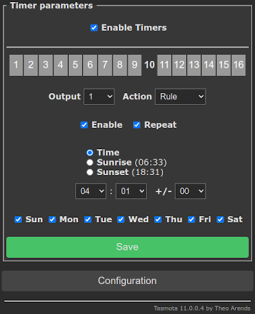
Since the NeoPool devices, without a WiFi module, have no way of synchronizing their internal clock with an external clock and, in addition, the accuracy of the internal clock leaves something to be desired, it makes sense to synchronize the clock with Tasmota once a day. Advantageously, we do this at night after a possible daylight saving time or normal time change.
We use a rule that synchronizes the time and which is triggered by the Tasmota built-in timer (here we use timer 10):
Rule2
  ON Clock#Timer=10 DO NPTime 0 ENDON
Activate it:
Backlog Rule2 4;Rule2 1
Configure Tasmota "Timer 10" for your needs:
ESP82xx/ESP32: Add buttons for filtration and light control~
Add two dummy buttons to control the filtration pump and the light.
First we define two dummy relay (which does not have any physical function) on two unused GPIO (here we use GPIO0 and GPIO4 where we define Tasmota Relay 1 and 2):
Backlog GPIO0 224;GPIO4 225
Then we rename the buttons for better visibility:
Backlog WebButton1 Filtration;WebButton2 Light
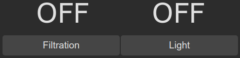
Now we have the WebGUI buttons like this:
but missing the functionality behind. For that we use Rules and connect the states for Tasmota Power, Neopool filtration and light:
Rule1
  ON Power1#State==0 DO NPFiltration %value% ENDON
  ON Power1#State==1 DO NPFiltration %value% ENDON
  ON NeoPool#Filtration#State==0 DO Power1 %value% ENDON
  ON NeoPool#Filtration#State==1 DO Power1 %value% ENDON
  ON Power2#State==0 DO NPLight %value% ENDON
  ON Power2#State==1 DO NPLight %value% ENDON
  ON NeoPool#Light==0 DO Power2 %value% ENDON
  ON NeoPool#Light==1 DO Power2 %value% ENDON
Don't wonder about the double trigger definition, which at first glance seem nonsensical - they are necessary so that the rule does not trigger endless.
At least we activate the rule:
Backlog Rule1 5;Rule1 1
It is important to enable the Rule ONCE (Rule1 5) function, which prevents the trigger is triggering themself in a loop.
You can now control filtration and light using the WebGUI and get the current status of the device elements when they are switched by auto-mode or manually on the device directly.
Additional advantage is that you can also use Tasmota Timer switching Power1 (=filtration) and Power2 (light) for your needs.
ESP32: Adding user defined NeoPool commands to Tasmota~
The following enhancements are made using the Berry Scripting Language which is available on ESP32 only.
The Berry script file neopoolcmd.be below adds the following new commands to Tasmota:
| Command | Parameters |
|---|---|
| NPAux<x> | <state>Set auxiliary relay <x> (x= 1..4, state = 0..2):
2 - toggle auxiliary relay |
| NPAntiFreeze<x> | <state>Set Smart mode antifreeze (state = 0..2):
2 - toggle Smart mode antifreeze |
| NPTimer<x> | 0 or OFF or <hh:mm hh:mm>( <period>) or <json>Set device timer for filtration, light and auxiliary relay (x= 1..12)<x>:
|
| NPVersion | Get the firmware info as array (firmware version and creation date) |
| NPBackup | (<name>( overwrite)Creates a backup copy of device setting (it saves the INSTALLER (0x04xx), USER (0x05xx) and MISC (0x06xx) pages). <name> is optional and may contain strftime format codes (default devicename_%Y-%m-%dT%H:%M:%S).The command fails if the backup file already exists. Explicitly use <name> and append overwrite to overwrite an existing backup file or delete the file manually.Note: The backup files are stored in Tasmota file system within the hidden directory .npbackup, pay attention to the maximum free size of the file system and use NPPrune if necessary |
| NPRestore | <name>Restores a previous device setting backup, <name> is required. Use command NPList to get a list the backup files.Note: A restart of the system may be necessary if massive changes are made by an NPRestore. |
| NPList | Get a list of all stored backup files. |
| NPPrune | <age>( dry-run)Deletes backup files that are older than specified <age> seconds. Use postfix (e. g. "1w") for s - secondsm - minutesh - hoursd - daysw - weeksy - yearsUse dry-run to simulate the NPPrune run, it will list the files that will be deleted. |
Store the following script into the Tasmota file system by using the WebGUI "Console" / "Manage File system".
neopoolcmd.be~
View script
# File: neopoolcmd.be
#
# Add commands NPAux, NPAntiFreeze, NPTimer, NPVersion, NPBackup, NPRestore, NPList and NPPrune

# Neopool definitions

MBF_POWER_MODULE_REGISTER = 0x000C
MBF_POWER_MODULE_DATA = 0x000D
MBF_RELAY_STATE = 0x010E
MBF_PAR_SMART_ANTI_FREEZE = 0x41A
MBF_PAR_UICFG_MACHINE = 0x0600

# MBF_PAR_TIMER_BLOCK_BASE
MBV_TIMER_OFFMB_TIMER_ENABLE = 0
MBV_TIMER_OFFMB_TIMER_ON = 1
MBV_TIMER_OFFMB_TIMER_OFF = 3
MBV_TIMER_OFFMB_TIMER_PERIOD = 5
MBV_TIMER_OFFMB_TIMER_INTERVAL = 7
MBV_TIMER_OFFMB_TIMER_COUNTDOWN = 9
MBV_TIMER_OFFMB_TIMER_FUNCTION = 11
MBV_TIMER_OFFMB_TIMER_WORK_TIME = 13

MBV_TIMER_OFFMB_TIMER_ON_IDX = 0
MBV_TIMER_OFFMB_TIMER_OFF_IDX = 1
MBV_TIMER_OFFMB_TIMER_PERIOD_IDX = 2
MBV_TIMER_OFFMB_TIMER_INTERVAL_IDX = 3
MBV_TIMER_OFFMB_TIMER_COUNTDOWN_IDX = 4
MBV_TIMER_OFFMB_TIMER_FUNCTION_IDX  = 5
MBV_TIMER_OFFMB_TIMER_WORK_TIME_IDX = 6

# MBV_TIMER_OFFMB_TIMER_ENABLE working modes:
MBV_PAR_CTIMER_DISABLE = 0
MBV_PAR_CTIMER_ENABLED  = 1
MBV_PAR_CTIMER_ENABLED_LINKED = 2
MBV_PAR_CTIMER_ALWAYS_ON  = 3
MBV_PAR_CTIMER_ALWAYS_OFF = 4
MBV_PAR_CTIMER_COUNTDOWN_KEY = 5
MBV_PAR_CTIMER_COUNTDOWN_KEY_PLUS = 0x01
MBV_PAR_CTIMER_COUNTDOWN_KEY_MINUS = 0x02
MBV_PAR_CTIMER_COUNTDOWN_KEY_ARROWDOWN = 0x04
MBV_PAR_CTIMER_COUNTDOWN_KEY_ARROWUP = 0x08
MBV_PAR_CTIMER_COUNTDOWN_KEYS = {
  MBV_PAR_CTIMER_COUNTDOWN_KEY_PLUS:"+",
  MBV_PAR_CTIMER_COUNTDOWN_KEY_MINUS:"-",
  MBV_PAR_CTIMER_COUNTDOWN_KEY_ARROWDOWN:"▼",
  MBV_PAR_CTIMER_COUNTDOWN_KEY_ARROWUP:"▲"
}

# MBV_TIMER_OFFMB_TIMER_FUNCTION codes:
MBV_PAR_CTIMER_FCT_FILTRATION = 0x0001
MBV_PAR_CTIMER_FCT_LIGHTING = 0x0002
MBV_PAR_CTIMER_FCT_HEATING = 0x0004
MBV_PAR_CTIMER_FCT_RELAY1 = 0x0100
MBV_PAR_CTIMER_FCT_RELAY2 = 0x0200
MBV_PAR_CTIMER_FCT_RELAY3 = 0x0400
MBV_PAR_CTIMER_FCT_RELAY4 = 0x0800
MBV_PAR_CTIMER_FCT_RELAY5 = 0x1000
MBV_PAR_CTIMER_FCT_RELAY6 = 0x2000
MBV_PAR_CTIMER_FCT_RELAY7 = 0x4000
# Function codes text
MBV_PAR_CTIMER_FCT = {
  MBV_PAR_CTIMER_FCT_FILTRATION:"Filtration",
  MBV_PAR_CTIMER_FCT_LIGHTING:"Light",
  MBV_PAR_CTIMER_FCT_HEATING:"Heating",
  MBV_PAR_CTIMER_FCT_RELAY1:"Relay1",
  MBV_PAR_CTIMER_FCT_RELAY2:"Relay2",
  MBV_PAR_CTIMER_FCT_RELAY3:"Relay3",
  MBV_PAR_CTIMER_FCT_RELAY4:"Aux1",
  MBV_PAR_CTIMER_FCT_RELAY5:"Aux2",
  MBV_PAR_CTIMER_FCT_RELAY6:"Aux3",
  MBV_PAR_CTIMER_FCT_RELAY7:"Aux4"
}

# configuration of the system timers
MBF_PAR_TIMER_BLOCK_FILT_INT1 = 0x0434
MBF_PAR_TIMER_BLOCK_FILT_INT2 = 0x0443
MBF_PAR_TIMER_BLOCK_FILT_INT3 = 0x0452
MBF_PAR_TIMER_BLOCK_LIGHT_INT = 0x0470
MBF_PAR_TIMER_BLOCK_AUX1_INT1 = 0x04AC
MBF_PAR_TIMER_BLOCK_AUX1_INT2 = 0x0461
MBF_PAR_TIMER_BLOCK_AUX2_INT1 = 0x04BB
MBF_PAR_TIMER_BLOCK_AUX2_INT2 = 0x047F
MBF_PAR_TIMER_BLOCK_AUX3_INT1 = 0x04CA
MBF_PAR_TIMER_BLOCK_AUX3_INT2 = 0x048E
MBF_PAR_TIMER_BLOCK_AUX4_INT1 = 0x04D9
MBF_PAR_TIMER_BLOCK_AUX4_INT2 = 0x049D

# Timer base addr index
PAR_TIMER_BLOCK = [
  # addr, function
  [MBF_PAR_TIMER_BLOCK_FILT_INT1, MBV_PAR_CTIMER_FCT_FILTRATION],
  [MBF_PAR_TIMER_BLOCK_FILT_INT2, MBV_PAR_CTIMER_FCT_FILTRATION],
  [MBF_PAR_TIMER_BLOCK_FILT_INT3, MBV_PAR_CTIMER_FCT_FILTRATION],
  [MBF_PAR_TIMER_BLOCK_LIGHT_INT, MBV_PAR_CTIMER_FCT_LIGHTING],
  [MBF_PAR_TIMER_BLOCK_AUX1_INT1, MBV_PAR_CTIMER_FCT_RELAY4],
  [MBF_PAR_TIMER_BLOCK_AUX1_INT2, MBV_PAR_CTIMER_FCT_RELAY4],
  [MBF_PAR_TIMER_BLOCK_AUX2_INT1, MBV_PAR_CTIMER_FCT_RELAY5],
  [MBF_PAR_TIMER_BLOCK_AUX2_INT2, MBV_PAR_CTIMER_FCT_RELAY5],
  [MBF_PAR_TIMER_BLOCK_AUX3_INT1, MBV_PAR_CTIMER_FCT_RELAY6],
  [MBF_PAR_TIMER_BLOCK_AUX3_INT2, MBV_PAR_CTIMER_FCT_RELAY6],
  [MBF_PAR_TIMER_BLOCK_AUX4_INT1, MBV_PAR_CTIMER_FCT_RELAY7],
  [MBF_PAR_TIMER_BLOCK_AUX4_INT2, MBV_PAR_CTIMER_FCT_RELAY7]
]
PAR_TIMER_BLOCK_AUX = [
  MBF_PAR_TIMER_BLOCK_AUX1_INT1,
  MBF_PAR_TIMER_BLOCK_AUX2_INT1,
  MBF_PAR_TIMER_BLOCK_AUX3_INT1,
  MBF_PAR_TIMER_BLOCK_AUX4_INT1
]

# Register to exclude from restore
MBF_PAR_TIME_LOW = 0x0408
MBF_PAR_TIME_HIGH = 0x0409
MBF_ACTION_COPY_TO_RTC = 0x04F0

RESTORE_EXCL = [
  MBF_PAR_TIME_LOW,
  MBF_PAR_TIME_HIGH,
  MBF_ACTION_COPY_TO_RTC
]

MACHINE_NAMES = [
  "NeoPool",
  "Hidrolife",
  "Aquascenic",
  "Oxilife",
  "Bionet",
  "Hidroniser",
  "UVScenic",
  "Station",
  "Brilix",
  "Generic",
  "Bayrol",
  "Hay"
]

import string
import json
import path

# NeoPool command class
class NeoPoolCommands
  var TEXT_OFF
  var TEXT_ON
  var TEXT_TOGGLE
  var BACKUP_DIR
  var BACKUP_NAME
  var BACKUP_START_ADDR
  var BACKUP_END_ADDR

  # helper
  def ltrim(s)
    var i = 0 while(i < size(s) && s[i] == ' ') i += 1 end
    return string.split(s, i)[1]
  end
  def rtrim(s)
    var i = size(s) while(i && s[i-1] == ' ') i -= 1 end
    return string.split(s, i)[0]
  end
  def trim(s)
    return self.rtrim(self.ltrim(s));
  end
  def list_sort(_list)
    for i:1..size(_list)-1
      var _value = _list[i]
      var j = i
      while (j > 0) && (_list[j-1] > _value)
        _list[j] = _list[j-1]
        j -= 1
      end
      _list[j] = _value
    end
    return _list
  end
  def get_args(payload)
    if nil == payload
      return []
    end
    var p = string.replace(payload, ' ', ',')
    var d = nil
    var s = ""
    for i:0..size(p)-1
      if nil == d && ('"' == p[i] || "'" == p[i])
        d = p[i]
      elif nil != d && d == p[i]
        d = nil
      elif nil != d && "," == p[i]
        s += ' '
      else
        s += p[i]
      end
    end
    p = string.split(s, ',')
    while p.find('') != nil p.remove(p.find('')) end
    return p
  end
  def get_args_switch(payload, p2)
    var parm, res
    try
      parm = string.tolower(self.trim(payload))
    except ..
      parm = ""
    end
    if parm != ""

      if (size(parm) == size('off') && string.find(parm, 'off') == 0) ||
        (size(parm) == size('0') && string.find(parm, '0') == 0) ||
        (size(parm) == size(self.TEXT_OFF) && string.find(parm, self.TEXT_OFF) == 0)
        res = 0
      elif (size(parm) == size('on') && string.find(parm, 'on') == 0) ||
          (size(parm) == size('1') && string.find(parm, '1') == 0) ||
          (size(parm) == size(self.TEXT_ON) && string.find(parm, self.TEXT_ON) == 0)
        res = 1
      elif p2 != nil &&
          ((size(parm) == size(p2) && string.find(parm, p2) == 0) ||
            (size(parm) == size('2') && string.find(parm, '2') == 0)
          )
        res = 2
      else
        res = -1
      end
    else
      res = nil
    end
    parm = nil
    tasmota.gc()
    return res
  end
  def get_period_from_int(period_num)
    if (period_num == 0)
      return "0"
    elif ((period_num % (86400 * 365)) == 0)
      return string.format("%dy", period_num / (86400 * 365))
    elif ((period_num % (86400 * 7)) == 0)
      return string.format("%dw", period_num / (86400 * 7))
    elif ((period_num % 86400) == 0)
      return string.format("%dd", period_num / 86400)
    elif ((period_num % 3600) == 0)
      return string.format("%dh", period_num / 3600)
    elif ((period_num % 60) == 0)
      return string.format("%dm", period_num / 60)
    else
      return string.format("%ds", period_num)
    end
  end
  def get_period_from_str(period_str)
    period_str = string.tolower(self.trim(period_str))
    var period_num = int(period_str)
    if period_str[size(period_str) - 1] == 'y'
      period_num *= 365 * 24 * 60 * 60
    elif period_str[size(period_str) - 1] == 'w'
      period_num *= 7 * 24 * 60 * 60
    elif period_str[size(period_str) - 1] == 'd'
      period_num *= 24 * 60 * 60
    elif period_str[size(period_str) - 1] == 'h'
      period_num *= 60 * 60
    elif period_str[size(period_str) - 1] == 'm'
      period_num *= 60
    end
    return period_num
  end
  def get_timer(cmd, idx)
    var timer_enable = self.read_register(cmd, "NPRead", PAR_TIMER_BLOCK[idx - 1][0] + MBV_TIMER_OFFMB_TIMER_ENABLE);
    if nil == timer_enable return nil end
    var data = self.read_register(cmd, "NPReadL", PAR_TIMER_BLOCK[idx - 1][0] + MBV_TIMER_OFFMB_TIMER_ON, 7)
    if nil == data return nil end

    var mode, state = "Unknown"
    var values = ""
    if (timer_enable == MBV_PAR_CTIMER_DISABLE || timer_enable == MBV_PAR_CTIMER_ENABLED)
      mode = "Timer"
      state = self.TEXT_OFF
      if (timer_enable == MBV_PAR_CTIMER_ENABLED &&
        (int(data[MBV_TIMER_OFFMB_TIMER_ON_IDX]) !=
          (int(data[MBV_TIMER_OFFMB_TIMER_ON_IDX]) + int(data[MBV_TIMER_OFFMB_TIMER_INTERVAL_IDX]))
        )
      )
        state = self.TEXT_ON
      end

      values = string.format(',"Start":"%s","End":"%s","Period":"%s"',
        tasmota.strftime("%H:%M", int(data[MBV_TIMER_OFFMB_TIMER_ON_IDX])),
        tasmota.strftime("%H:%M", int(data[MBV_TIMER_OFFMB_TIMER_ON_IDX]) + int(data[MBV_TIMER_OFFMB_TIMER_INTERVAL_IDX])),
        self.get_period_from_int(int(data[MBV_TIMER_OFFMB_TIMER_PERIOD_IDX]))
      )
    end

    if (timer_enable == MBV_PAR_CTIMER_ALWAYS_OFF || timer_enable == MBV_PAR_CTIMER_ALWAYS_ON)
      mode = "Manual"
      state = (timer_enable == MBV_PAR_CTIMER_ALWAYS_OFF) ? self.TEXT_OFF : self.TEXT_ON
      values = ""
    end

    if ((timer_enable & 0x00FF) == MBV_PAR_CTIMER_COUNTDOWN_KEY)
      mode = "Temporary"
      state = self.TEXT_ON
      values = string.format(',"Key":"%s","Duration":"%s"',
        MBV_PAR_CTIMER_COUNTDOWN_KEYS.find(((timer_enable >> 8) & 0x0F), "unknown"),
        self.get_period_from_int(int(data[MBV_TIMER_OFFMB_TIMER_INTERVAL_IDX]))
      )
    end

    var alloc = MBV_PAR_CTIMER_FCT.find(int(data[MBV_TIMER_OFFMB_TIMER_FUNCTION_IDX]), "undefined")
    return string.format('{"%s%d":{"Mode":"%s","State":"%s","Allocation":"%s"%s}}', cmd, idx, mode, state, alloc, values)
  end
  def read_register(cmd, read_cmnd, addr, cnt)
    var res = tasmota.cmd(string.format("%s 0x%04X,%d", read_cmnd, addr, cnt), true).find(read_cmnd, "Unknown")
    # result must be a json
    if "Unknown" == res
      tasmota.resp_cmnd(string.format('{"%s":"NeoPool module not available or not activated"}', cmd))
      return nil
    end
    var _json = json.load(json.dump(res))
    if nil == _json || "Error" == res
      tasmota.resp_cmnd(string.format('{"%s":"NeoPool device does not respond"}', cmd))
      return nil
    end
    return compile("return ".._json.find('Data'))()
  end

  # NPAux<x> OFF|0|ON|1|TOGGLE|2 (<x> = 1..4)
  def NPAux(cmd, idx, payload)
    var ctrl, parm

    if idx < 1 || idx > 4
      tasmota.resp_cmnd_error()
      return
    end
    parm = self.get_args_switch(payload, self.TEXT_TOGGLE)
    if parm != nil
      if 0 == parm
        ctrl = MBV_PAR_CTIMER_ALWAYS_OFF
      elif 1 == parm
        ctrl = MBV_PAR_CTIMER_ALWAYS_ON
      elif 2 == parm
        try
          ctrl = self.read_register(cmd, "NPRead", MBF_RELAY_STATE)
          if nil == ctrl return end
          ctrl = (ctrl >> (idx+2)) & 1 ? MBV_PAR_CTIMER_ALWAYS_OFF : MBV_PAR_CTIMER_ALWAYS_ON
        except ..
          return
        end
      else
        tasmota.resp_cmnd_error()
        return
      end
      tasmota.cmd(string.format("NPWrite 0x%04X,%d", PAR_TIMER_BLOCK_AUX[idx-1], ctrl), true)
      tasmota.cmd("NPExec", true)
    else
      try
        ctrl = self.read_register(cmd, "NPRead", MBF_RELAY_STATE)
        if nil == ctrl return end
        ctrl = (ctrl >> (idx+2)) & 1
    except ..
        return
      end
    end
    tasmota.resp_cmnd(string.format('{"%s%d":"%s"}', cmd, idx, ctrl == (parm != nil ? 4 : 0) ? self.TEXT_OFF : self.TEXT_ON))
  end

  # NPAntiFreeze OFF|0|ON|1|TOGGLE|2
  def NPAntiFreeze(cmd, idx, payload)
    var ctrl, parm
    parm = self.get_args_switch(payload, self.TEXT_TOGGLE)
    if parm != nil
      if 0 == parm
        ctrl = 0
      elif 1 == parm
        ctrl = 1
      elif 2 == parm
        try
          ctrl = self.read_register(cmd, "NPRead", MBF_PAR_SMART_ANTI_FREEZE)
          if nil == ctrl return end
          if 1 == ctrl
            ctrl = 0
          else
            ctrl = 1
          end
        except ..
          return
        end
      else
        tasmota.resp_cmnd_error()
        return
      end
      tasmota.cmd(string.format("NPWrite 0x%04X,%d", MBF_PAR_SMART_ANTI_FREEZE, ctrl), true)
      tasmota.cmd("NPExec", true)
    else
      try
        ctrl = self.read_register(cmd, "NPRead", MBF_PAR_SMART_ANTI_FREEZE)
        if nil == ctrl return end
    except ..
        tasmota.resp_cmnd_error()
        return
      end
    end
    tasmota.resp_cmnd(string.format('{"%s":"%s"}', cmd, ctrl ? self.TEXT_ON : self.TEXT_OFF))
  end

  # NPTimer<x> 0|OFF|<hh:mm hh:mm>( <period>)|<json> (<x> = 1..12)
  def NPTimer(cmd, idx, payload)
    var parm

    if idx < 1 || idx > size(PAR_TIMER_BLOCK)
      tasmota.resp_cmnd_error()
      return
    end

    try
      parm = string.tolower(self.trim(payload))
    except ..
      parm = nil
    end

    if parm != nil && size(parm)

      # Set timer
      if self.get_args_switch(payload) == 0
        parm = ''
      end

      try
        if (nil == json.load(parm))
          # convert none json parm to json parm
          var params = self.get_args(parm)
          var keys = ["start", "end", "period"]
          if size(params) > size(keys)
            tasmota.resp_cmnd_error()
            return
          end
          var _json = {}
          while params.size() > 0
            _json[keys[0]] = params[0]
            keys.remove(0)
            params.remove(0)
          end
          parm = json.dump(_json)
        end
      except ..
        tasmota.resp_cmnd_error()
        return
      end

      parm = json.load(parm)
      if (nil != parm)
        var timer_start, timer_end, strp
        try
            # set start and end
          strp = tasmota.strptime(parm.find("start", "00:00"), "%H:%M")
          timer_start = (strp.find("hour", 0) * 3600) + (strp.find("min", 0) * 60)
          strp = tasmota.strptime(parm.find("end", "00:00"), "%H:%M")
          timer_end = strp.find("hour", 0) * 3600 + strp.find("min", 0) * 60
          if (timer_start > timer_end)
            var tmp = timer_end
            timer_end = timer_start
            timer_start = tmp
          end
        except ..
          tasmota.resp_cmnd_error()
          return
        end
        tasmota.cmd(string.format("NPWrite 0x%04X,%d", PAR_TIMER_BLOCK[idx - 1][0] + MBV_TIMER_OFFMB_TIMER_ENABLE, MBV_PAR_CTIMER_ENABLED), true)
        tasmota.cmd(string.format("NPWriteL 0x%04X,%d", PAR_TIMER_BLOCK[idx - 1][0] + MBV_TIMER_OFFMB_TIMER_FUNCTION, PAR_TIMER_BLOCK[idx - 1][1]), true)
        tasmota.cmd(string.format("NPWriteL 0x%04X,%d", PAR_TIMER_BLOCK[idx - 1][0] + MBV_TIMER_OFFMB_TIMER_ON, timer_start), true)
        tasmota.cmd(string.format("NPWriteL 0x%04X,%d", PAR_TIMER_BLOCK[idx - 1][0] + MBV_TIMER_OFFMB_TIMER_INTERVAL, timer_end - timer_start), true)

        if (self.get_period_from_str(parm.find("Period", "0")) != 0)
          tasmota.cmd(string.format("NPWriteL 0x%04X,%d", PAR_TIMER_BLOCK[idx - 1] + MBV_TIMER_OFFMB_TIMER_PERIOD, self.get_period_from_str(parm.find("Period", "0"))), true)
        end
        tasmota.cmd("NPExec", true)

        var res = self.get_timer(cmd, idx)
        if nil != res
          tasmota.resp_cmnd(res)
        end
      else
        tasmota.resp_cmnd_error()
      end

    else
      # Get timer
      var res = self.get_timer(cmd, idx)
      if nil != res
        tasmota.resp_cmnd(res)
      end

    end

  end

  # NPVersion
  def NPVersion(cmd)
    var verstr = ""
    for i: 0 .. 12
      tasmota.cmd(string.format("NPWrite 0x%04X,%d", MBF_POWER_MODULE_REGISTER, i*2), true)
      var data = self.read_register(cmd, "NPRead", MBF_POWER_MODULE_DATA)
      if nil == data return end
      verstr += string.char(data>>8 & 0xFF)
      verstr += string.char(data    & 0xFF)
    end
    var arr = []
    for i: string.split(verstr,'\n') arr.push(i) end
    tasmota.resp_cmnd(string.format('{"%s":%s}', cmd, json.dump(arr)))
  end

  # NPBackup (<name>( overwrite)
  #   <name> may contain strftime specifier
  def NPBackup(cmd, idx, payload)
    var name, overwrite = nil

    var machine = self.read_register(cmd, "NPRead", MBF_PAR_UICFG_MACHINE)
    if nil == machine return end
    machine = machine > size(MACHINE_NAMES) ? 0 : machine

    var parm = self.get_args(payload)
    if parm != nil && size(parm)
      name = self.trim(parm[0])
      if size(parm) > 1
        overwrite = string.tolower(self.trim(parm[1]))
      end
    else
      name = tasmota.strftime(MACHINE_NAMES[machine]+"_"+self.BACKUP_NAME, tasmota.rtc()['local'])
      name += string.format("%+03d:%02d", (tasmota.rtc()['local'] - tasmota.rtc()['utc']) / 3600, 0)
    end

    path.mkdir(self.BACKUP_DIR)
    name = tasmota.strftime(name, tasmota.rtc()['local'])
    if nil != overwrite
      if size(overwrite) > 0 && 'o' == overwrite[0]
        if path.exists(self.BACKUP_DIR+"/"+name)
          # overwrite, first delete existing
          path.remove(self.BACKUP_DIR+"/"+name)
        end
      else
        tasmota.resp_cmnd(string.format('{"%s":"Error","File":"%s","Msg":"Unknown command %s"}', cmd, name, overwrite))
        return
      end
    end
    if path.exists(self.BACKUP_DIR+"/"+name)
      # do not overwrite existing backups
      tasmota.resp_cmnd(string.format('{"%s":"Error","File":"%s","Msg":"Already exists"}', cmd, name))
      return
    end

    # read register
    var reg_data = []
    try
      for addr:range(self.BACKUP_START_ADDR, self.BACKUP_END_ADDR, 16)
        var r = self.read_register(cmd, "NPRead", addr, 16)
        if nil == r return end
        for i:r
          reg_data.push(int(i))
        end
      end
    except ..
      reg_data = []
    end

    if 0 == size(reg_data)
      tasmota.resp_cmnd(string.format('{"%s":"Error","Msg":"Reading Modbus register error"}', cmd))
      return
    end

    # write backup file
    try
      var f = open(self.BACKUP_DIR+"/"+name, "w")
      f.write(json.dump({string.format("0x%04X", self.BACKUP_START_ADDR):reg_data}))
      f.close()
    except ..
      tasmota.resp_cmnd(string.format('{"%s":"Error","File":"%s","Msg":"Writing file error"}', cmd, name))
      return
    end
    tasmota.resp_cmnd(string.format('{"%s":"Done","File":"%s"}', cmd, name))
    return
  end

  # NPRestore <name>
  def NPRestore(cmd, idx, payload)
    var name = nil

    var machine = self.read_register(cmd, "NPRead", MBF_PAR_UICFG_MACHINE)
    if nil == machine return end

    var parm = self.get_args(payload)

    if parm != nil && size(parm)
      name = self.trim(parm[0])
    else
      tasmota.resp_cmnd_error()
      return
    end
    if !path.exists(self.BACKUP_DIR+"/"+name)
      tasmota.resp_cmnd(string.format('{"%s":"Error","File":"%s","Msg":"Does not exists"}', cmd, name))
      return
    end

    # Restore
    # read backup file
    var backup = {}
    var f = open(self.BACKUP_DIR+"/"+name, "r")
    try
      backup = json.load(f.read())
      f.close()
    except ..
      tasmota.resp_cmnd(string.format('{"%s":"Error","File":"%s","Msg":"JSON format error"}', cmd, name))
      return
    end

    # if any multiple addr sort it
    var addr_list = []
    for i:backup.keys()
      addr_list.push(i)
    end
    addr_list = self.list_sort(addr_list)
    # do restore commands
    for addr:addr_list
      var reg_list = backup[addr]
      var write_cmnd = ""
      var cnt = 0
      var write_addr = int(addr)
      for reg_value:reg_list
        if nil == RESTORE_EXCL.find(write_addr)
          if "" == write_cmnd
            write_cmnd = string.format("NPWrite 0x%04X", write_addr)
          end
          write_cmnd +="," + str(int(reg_value))
          cnt += 1
          if cnt >= 8
            tasmota.cmd(write_cmnd, true)
            write_cmnd = ""
            cnt = 0
          end
        elif size(write_cmnd)
          tasmota.cmd(write_cmnd, true)
          write_cmnd = ""
          cnt = 0
        end
        write_addr += 1
      end
      if size(write_cmnd)
        tasmota.cmd(write_cmnd, true)
      end
    end
    tasmota.cmd("NPExec", true)
    tasmota.cmd("NPSave", true)
    tasmota.resp_cmnd(string.format('{"%s":"Done","File":"%s"}', cmd, name))
    return
  end

  # NPList
  def NPList(cmd)
    tasmota.resp_cmnd(string.format('{"%s":%s}', cmd, json.dump(path.listdir(self.BACKUP_DIR)) ))
  end

  # NPPrune <age>( dry-run)
  def NPPrune(cmd, idx, payload)
    var age = nil
    var dry_run = false

    var parm = self.get_args(payload)
    if parm != nil && size(parm)
      age = self.get_period_from_str(string.tolower(self.trim(parm[0])))
      if size(parm) > 1
        if size(string.tolower(self.trim(parm[1]))) > 0 && 'd' == string.tolower(self.trim(parm[1]))[0]
          dry_run = true
        else
          tasmota.resp_cmnd_error()
          return
        end
      end
    else
      tasmota.resp_cmnd_error()
      return
    end

    var dfiles = []
    for _filename:path.listdir(self.BACKUP_DIR)
      if (tasmota.rtc()['local'] - path.last_modified(self.BACKUP_DIR+"/"+_filename)) > age
        dfiles.push(_filename)
        if !dry_run
          path.remove(self.BACKUP_DIR+"/"+_filename)
        end
      end
    end
    if dry_run
      tasmota.resp_cmnd(string.format('{"%s":"dry-run","File":%s}', cmd, json.dump(dfiles)))
      return
    end
    tasmota.resp_cmnd(string.format('{"%s":"Done","File":%s}', cmd, json.dump(dfiles)))
  end


  def init()
    # get tasmota settings
    self.TEXT_OFF = tasmota.cmd('StateText1', true).find('StateText1', 'OFF')
    self.TEXT_ON = tasmota.cmd('StateText2', true).find('StateText2', 'ON')
    self.TEXT_TOGGLE = tasmota.cmd('StateText3', true).find('StateText3', 'TOGGLE')
    self.BACKUP_DIR = "/.npbackup"
    self.BACKUP_NAME = '%Y-%m-%dT%H:%M:%S'
    self.BACKUP_START_ADDR = 0x0400
    self.BACKUP_END_ADDR = 0x06FF
    # add commands
    tasmota.add_cmd('NPAux', / cmd, idx, payload -> self.NPAux(cmd, idx, payload))
    tasmota.add_cmd('NPAntiFreeze', / cmd, idx, payload -> self.NPAntiFreeze(cmd, idx, payload))
    tasmota.add_cmd('NPTimer', / cmd, idx, payload -> self.NPTimer(cmd, idx, payload))
    tasmota.add_cmd('NPVersion', / cmd -> self.NPVersion(cmd))
    tasmota.add_cmd('NPBackup', / cmd, idx, payload -> self.NPBackup(cmd, idx, payload))
    tasmota.add_cmd('NPRestore', / cmd, idx, payload -> self.NPRestore(cmd, idx, payload))
    tasmota.add_cmd('NPList', / cmd -> self.NPList(cmd))
    tasmota.add_cmd('NPPrune', / cmd, idx, payload -> self.NPPrune(cmd, idx, payload))
  end

  def deinit()
    # remove commands
    tasmota.remove_cmd('NPAux')
    tasmota.remove_cmd('NPAntiFreeze')
    tasmota.remove_cmd('NPTimer')
    tasmota.remove_cmd('NPVersion')
    tasmota.remove_cmd('NPBackup')
    tasmota.remove_cmd('NPRestore')
    tasmota.remove_cmd('NPList')
    tasmota.remove_cmd('NPPrune')
  end
end
neopoolcommands = NeoPoolCommands()
To activate the new commands, go to WebGUI "Consoles" / "Berry Scripting console" and execute
load("neopoolcmd.be")
ESP32: Add GUI controls for filtration, light and aux relais~
The following enhancements are made using the Berry Scripting Language which is available on ESP32 only.
The class NeoPoolButtonMethods below adds new GUI elements to control filtration, light and aux relais:
Store the following code into a Tasmota file by using the WebGUI "Console" / "Manage File system".
neopoolgui.be~
View script
# File: neopoolgui.be
#
# Add GUI elements for filtration control, light and aux relais
import webserver
import string
class NeoPoolButtonMethods : Driver
#- method for adding elements to the main menu -#
def web_add_main_button()
def selected(value, comp)
return comp == value ? 'selected=""' : ''
end
var html = '<p></p>'
var speed = tasmota.cmd('NPFiltration').find('Speed', 'invalid')
var mode = tasmota.cmd('NPFiltrationmode').find('NPFiltrationmode', 'invalid')
if 'invalid' == speed && 'invalid' == mode
html+= 'NeoPool device not available'
else
# Filtration mode/speed
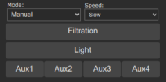
html+= '<table style="width:100%"><tbody><tr>'
html+= ' <td style="width:50%;padding: 0 4px 0 4px;">'
html+= ' <label for="mode"><small>Mode:</small></label>'
html+= ' <select id="mode" name="mode">'
html+= string.format('<option value="m_sv_manual"%s>Manual</option>', selected(mode, 'Manual'))
html+= string.format('<option value="m_sv_auto"%s>Auto</option>', selected(mode, 'Auto'))
html+= string.format('<option value="m_sv_heating"%s>Heating</option>', selected(mode, 'Heating'))
html+= string.format('<option value="m_sv_smart"%s>Smart</option>', selected(mode, 'Smart'))
html+= string.format('<option value="m_sv_intelligent"%s>Intelligent</option>', selected(mode, 'Intelligent'))
html+= ' </select>'
html+= ' </td>'
html+= ' <td style="width:50%;padding: 0 4px 0 4px;">'
html+= ' <label for="speed"><small>Speed:</label>'
html+= ' <select id="speed" name="speed">'
html+= string.format('<option value="m_sv_slow"%s>Slow</option>', selected(speed, '1'))
html+= string.format('<option value="m_sv_medium"%s>Medium</option>', selected(speed, '2'))
html+= string.format('<option value="m_sv_fast"%s>Fast</option>', selected(speed, '3'))
html+= ' </select>'
html+= ' </td>'
html+= '</tr><tr></tr></tbody></table>'
html+= '<script>'
html+= 'document.getElementById("speed").addEventListener ("change",function(){la("&"+this.value+"=1");});'
html+= 'document.getElementById("mode").addEventListener ("change",function(){la("&"+this.value+"=1");});'
html+= '</script>'
# Filtration button
html+= '<table style="width:100%"><tbody><tr>'
html+= ' <td style="width:100%">'
html+= ' <button id="bn_filtration" name="bn_filtration" onclick="la(\'&m_sv_filtration=1\');">Filtration</button>'
html+= ' </td>'
html+= '</tr><tr></tr></tbody></table>'
# Light button
html+= '<table style="width:100%"><tbody><tr>'
html+= ' <td style="width:100%">'
html+= ' <button onclick="la(\'&m_sv_light=1\');">Light</button>'
html+= ' </td>'
html+= '</tr><tr></tr></tbody></table>'
# Aux buttons
html+= '<table style="width:100%"><tbody><tr>'
html+= ' <td style="width:25%"><button onclick="la(\'&m_sv_aux=1\');">Aux1</button></td>'
html+= ' <td style="width:25%"><button onclick="la(\'&m_sv_aux=2\');">Aux2</button></td>'
html+= ' <td style="width:25%"><button onclick="la(\'&m_sv_aux=3\');">Aux3</button></td>'
html+= ' <td style="width:25%"><button onclick="la(\'&m_sv_aux=4\');">Aux4</button></td>'
html+= '</tr><tr></tr></tbody></table>'
end
webserver.content_send(html)
html = nil
speed = nil
mode = nil
tasmota.gc()
end
#- As we can add only one sensor method we will have to combine them besides all other sensor readings in one method -#
def web_sensor()
if webserver.has_arg("m_sv_filtration")
tasmota.cmd("NPFiltration 2")
end
if webserver.has_arg("m_sv_slow")
tasmota.cmd("NPFiltration 1,1")
end
if webserver.has_arg("m_sv_medium")
tasmota.cmd("NPFiltration 1,2")
end
if webserver.has_arg("m_sv_fast")
tasmota.cmd("NPFiltration 1,3")
end
if webserver.has_arg("m_sv_manual")
tasmota.cmd("NPFiltrationmode 0")
end
if webserver.has_arg("m_sv_auto")
tasmota.cmd("NPFiltrationmode 1")
end
if webserver.has_arg("m_sv_heating")
tasmota.cmd("NPFiltrationmode 2")
end
if webserver.has_arg("m_sv_smart")
tasmota.cmd("NPFiltrationmode 3")
end
if webserver.has_arg("m_sv_intelligent")
tasmota.cmd("NPFiltrationmode 4")
end
if webserver.has_arg("m_sv_light")
tasmota.cmd("NPLight 2")
end
if webserver.has_arg("m_sv_aux")
tasmota.cmd("NPAux"+webserver.arg("m_sv_aux")+" TOGGLE")
end
end
def init()
end
def deinit()
end
end
neopool_driver = NeoPoolButtonMethods()
tasmota.add_driver(neopool_driver)
To activate the new gui elements, go to WebGUI "Consoles" / "Berry Scripting console" and execute
load("neopoolgui.be")
ESP32: Make the scripts persistent~
If you want the extensions to be activated automatically every time you restart your ESP32, save the load() commands into the special file autoexec.be:
autoexec.be~
load("neopoolcmd.be")
load("neopoolgui.be")