PCA9557 GPIO Expander~
Technical Data from the manufacturer: * NXP PCA9557
The PCA9557 has 8 IO pins which the PCA9557 driver uses as D0 - D7. This is visualized in the circuit diagram below.

You will need to pick an I2C address using the address mapping according to pin A0, A1, and A2 as from the datasheet as follows:

Supporting modes~
Starting with Tasmota v12.5.0.x several and mixed PCA9557 are supported, adding switches, buttons and relays acted on as if they were directly connected to the ESP8266 or ESP32 configured using a JSON file containing a template describing the GPIO's as used on the basic Tasmota device.
To enable it you will only need to add in user_config_override.h
#define USE_PCA9557
This enables the driver which in turn at restart will search for the JSON file in three possible locations:
- if a filesystem is present it looks for file
pca9557.dat - if not found and rules are supported it looks for a specific rule entry like
on file#pca9557.dat do <template> endon - if not found and scripts are supported it looks for a specific script like
-y <template>
If no JSON file is found the driver does not claim any PCA9557 device.
A typical JSON template would look like {"NAME":"PCA9557 expander","BASE":0,"GPIO":[224,225,226,227,32,33,34,35]} which adds four relays and four buttons.
The template consists of a "NAME" data pair with any description of the template, an optional "BASE" data pair selecting if either relative (0 = default) or absolute (1) button and/or switch numbering is used and a "GPIO" data pair with numbers representing the functions of the GPIO's in order from lowest I2C address IO0 to highest I2C address IO7 and are based on the numbers known from the base tasmota template used on the ESP8266 or ESP32.
The following list contains the current supported functions:
| Function | Code | Description | |
|---|---|---|---|
| None | 0 | Not used | |
| Button_n1..32 | Bn | 64..95 | Button to Gnd (needs external resistor) |
| Button_in1..32 | Bin | 128..159 | Button inverted to Vcc (needs external resistor) |
| Switch_n1..28 | Sn | 192..219 | Switch to Gnd (needs external resistor) |
| Relay1..32 | R | 224..255 | Relay |
| Relay_i1..32 | Ri | 256..287 | Relay inverted |
| Output_Hi | Oh | 3840 | Fixed output high |
| Output_lo | Ol | 3872 | Fixed output low |
Some example templates
                          S3  S2  B2 B3 Oh   B1 S1    R1        R4  R2  R3  S4
{"NAME":"PCA9557","GPIO":[194,193,65,66,3840,64,192,0,224,0,0,0,227,225,226,195]}

Inverted relays and buttons               Ri1 Ri2 Ri3 Ri4 Ri5 Ri6 Ri7 Ri8 B1 B2 B3 B4 B5 B6 B7 B8
{"NAME":"PCA9557 A=Ri1-8, B=B1-8","GPIO":[256,257,258,259,260,261,262,263,32,33,34,35,36,37,38,39]}

Unique inverted relays and buttons with offset 2     Ri3 Ri4 Ri5 Ri6 Ri7 Ri8 Ri9 Ri10B3 B4 B5 B6 B7 B8 B9 B10
{"NAME":"PCA9557 A=Ri2-10, B=B2-10","BASE":1,"GPIO":[258,259,260,261,262,263,264,265,34,35,36,37,38,39,40,41]}

Buttons, relays, buttons and relays                        B1 B2 B3 B4 B5 B6 B7 B8 R1  R2  R3  R4  R5  R6  R7  R8  B9 B10B11B12B13B14B15B16R9  R10 R11 R12 R13 R14 R15 R16
{"NAME":"PCA9557 A=B1-8, B=R1-8, C=B9-16, D=R9-16","GPIO":[32,33,34,35,36,37,38,39,224,225,226,227,228,229,230,231,40,41,42,43,44,45,46,47,232,233,234,235,236,237,238,239]}
Since the PCA9557 has no interrupt pin, buttons and switches will be polled every 50ms.
You will need to define the address you are using in user_config_override.h for the driver to know on which address the PCA9557 is expected to be found.
#define USE_PCA9557_ADDR 0x18
The PCA9557 chips allow for both INPUT and OUTPUT.
If OUTPUT is enabled, telemetry data for the current state of OUTPUT pins will also be provided by telemetry.
Usage of the driver~
The PCA9557 chip (or breakout board) must be connected to the ESP8266/ESP32 and the I2C pins must be configured for the module similar to the following:
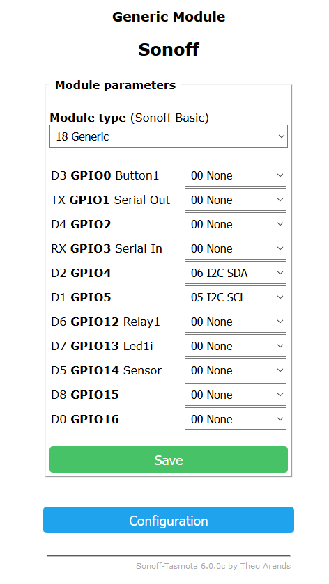
Once that is complete you may want to confirm that the Tasmota firmware is finding your PCA9557 chip by sending the command through serial or MQTT:
I2Cscan
You should see a response giving you an address within the range of the PCA9557 chip (0x18 through 0x1F) which may look as follows
MQT: stat/tasmota/RESULT = {"I2CScan":"Device(s) found at 0x18"}
If the extender is not detected, check your wiring and pin configuration.
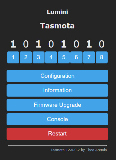
If sucessful, you should be able to see the changes in Tasmota main web page. Following example has 8 IO lines defined as relays:
Configuration example~
You can add all necessary settings at once in your user_config_override.h. The following example adds 8 relays (commanded with POWER1 to POWER8), PCA9557 has all address bits tied to GND (0x18) while ESP8266 GPIO 0 and 2 are used for I2C SDA and SCL.
#define USE_PCA9557
#define USE_PCA9557_ADDR 0x18

#define USER_TEMPLATE "{\"NAME\":\"Lights\",\"GPIO\":[608,0,640,0,0,0,0,0,0,0,0,0,0,0],\"FLAG\":0,\"BASE\":18}"
#define USER_RULE1 "On file#pca9557.dat DO {\"NAME\":\"Lights\",\"BASE\":0,\"GPIO\":[256,257,258,259,260,261,262,263]} ENDON"