PCF8574 / PCF8574A GPIO Expander~
This feature is not included in precompiled binaries
When compiling your build add the following to user_config_override.h:
#define USE_I2C                                // Add support for I2C
#define USE_PCF8574                            // [I2cDriver2] Enable PCF8574 I/O Expander (I2C addresses 0x20 - 0x26 and 0x39 - 0x3F) (+2k1 code)
//  #define USE_PCF8574_MODE2                    // Enable Mode2 virtual relays/buttons/switches (+2k3 code)
//  #define USE_PCF8574_SENSOR                   // Enable Mode1 inputs and outputs in SENSOR message (+0k2 code)
//  #define USE_PCF8574_DISPLAYINPUT             // Enable Mode1 inputs display in Web page (+0k2 code)
//  #define USE_PCF8574_MQTTINPUT                // Enable Mode1 MQTT message & rule process on input change detection : stat/%topic%/PCF8574_INP = {"Time":"2021-03-07T16:19:23+01:00","PCF8574-1_INP":{"D1":1}} (+0k5 code)
Introduction~
PCF8574 and PCF8574A are I2C 8-bit IO port extender originally designed by Philips (now NXP) but also now available from various manufacturer.
As usual when using an electronic part, reading the datasheet is highly recommended as the below document only focus on Tasmota integration.
A few different breakout boards are available although some are dedicated to be mounted as a backpack on standard 16x2 or 16x4 LCD displays and are not suitable for general I/Os (but works well with tasmota-display).
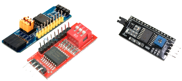
- On the left: generic modules suitable for extending IO
- On the right: specific module to control a LCD display (not the purpose of this doc page)
Supported I2C addresses and number of PCF8574~
PCF8574 and PCF8574A are identical functionally and each can be configured to work on 1 of 8 possible I2C address. PCF8574 can use one address of 0x20 to 0x27 and PCF8574A can use one of 0x38 to 0x3F.
As of today, Tasmota driver supports:
- Up to 4 PCF8574 OR PCF8574A is supported by Tasmota allowing up to 32 additional GPIO pins.
- Addresses 0x27 and 0x38 are excluded to avoid conflict with other I2C peripheral which can't be differentiated at run-time.
If USE_MCP230xx_ADDR is defined, this address is reserved for MCP230XX IO expander.
The first 2 lines are mandatory to enable I2C support and including the driver in the build. The 3 other lines allows to add optional features to support inputs. By default only the "outputs" feature is enabled.
Tasmota Configuration~
Note
Once the firmware with the PCF8574 driver has been loaded, make sure to have it enabled with I2Cdriver2 1.
Starting with Tasmota v12.4.0.2 there are two different modes to use PCF8574(A):
- The original approach (now called Mode 1) supports user configurable features using a GUI menu.
- The latest approach called Mode 2, supports adding switches, buttons and relays configured using a JSON file containing a template describing the GPIO's as used on the basic Tasmota device.
Mode 2~
To enable Mode 2 you will need to add in user_config_override.h
#define USE_PCF8574_MODE2
This enables the driver which will at restart search for the JSON file in three possible locations:
- if a filesystem is present it looks for file
pcf8574.dat - if not found and rules are supported it looks for a specific rule entry like
on file#pcf8574.dat do <template> endon - if not found and scripts are supported it looks for a specific script like
-y <template>
Note
If no JSON file is found the driver continues in mode 1.
A typical JSON template would look like {"NAME":"PCF8574 expander","BASE":0,"GPIO":[224,225,226,227,32,33,34,35]} which adds four relays and four buttons.
The template consists of a "NAME" data pair with any description of the template, an optional "BASE" data pair selecting if either relative (0 = default) or absolute (1) button and/or switch numbering is used and a "GPIO" data pair with numbers representing the functions of the GPIO's in order from lowest I2C address D0 to highest I2C address D7 and are based on the numbers known from the base tasmota template used on the ESP8266 or ESP32.
The following list contains the current supported functions:
| Function | Code | Description | |
|---|---|---|---|
| None | 0 | Not used | |
| Button1..32 | B | 32..63 | Button to Gnd with internal pullup |
| Button_n1..32 | Bn | 64..95 | Button to Gnd without internal pullup |
| Button_i1..32 | Bi | 96..127 | Button inverted to Vcc with internal pullup |
| Button_in1..32 | Bin | 128..159 | Button inverted to Vcc without internal pullup |
| Switch1..28 | S | 160..187 | Switch to Gnd with internal pullup |
| Switch_n1..28 | Sn | 192..219 | Switch to Gnd without internal pullup |
| Relay1..32 | R | 224..255 | Relay |
| Relay_i1..32 | Ri | 256..287 | Relay inverted |
| Output_Hi | Oh | 3840 | Fixed output high |
| Output_lo | Ol | 3872 | Fixed output low |
Some example templates
Unique inverted relays and buttons with offset 2                           B3 B4 B5 B6 Ri3 Ri4 Ri5 Ri6 B7 Ri7 B8 Ri8 B9 Ri9 B10Ri10
{"NAME":"PCF8574 A=B3456,Ri3456,B=B7Ri7B8Ri8B9Ri9B10Ri10","BASE":1,"GPIO":[34,35,36,37,258,259,260,261,38,262,39,263,40,264,41,265]}

Inverted relays and buttons               Ri8 Ri7 Ri6 Ri5 Ri4 Ri3 Ri2 Ri1 B1 B2 B3 B4 B5 B6 B7 B8
{"NAME":"PCF8574 A=Ri8-1, B=B1-8","GPIO":[263,262,261,260,259,258,257,256,32,33,34,35,36,37,38,39]}

                                                     B1 B2 B3 B4 Ri4 Ri3 Ri2 Ri1 B5 B6 B7 B8 Ri8 Ri7 Ri6 Ri5
{"NAME":"PCF8574 A=B1-4,Ri4-1, B=B5-8,Ri8-5","GPIO":[32,33,34,35,259,258,257,256,36,37,38,39,263,262,261,260]}
Mode 1~
PCF8574 can be configured from Tasmota web GUI in "Configure" => "Configure PCF8574" 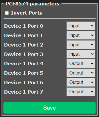
Each IO port can be configured as Input or Output in a similar way as a native GPIO of the ESP.
If you are using outputs to drive relays, it is possible to choose if the relay is activated by a HIGH signal (checkbox "Invert Ports" unchecked) or a LOW signal (checkbox checked). The selection applies to all output ports. This checkbox can also be controlled by SetOption81.
Once configuration is complete, it must be saved by clicking on the green "Save" button. Like for general ESP GPIO configuration, this will trigger a reboot of the ESP.
It is not possible to change pin definition at run-time.
Outputs~
A PCF8574 pin configured as an output support all features of a Tasmota Relay component.
It is assigned a Power index and can be controlled by Power command (on, off, toggle). Power indexes of PCF8574 outputs are assigned after the ESP GPIO configured as Relay. For example, if you have Relay 1 (Power1) to Relay 4 (Power4) configured on the ESP's GPIO, PCF8574 outputs will start at Power5.
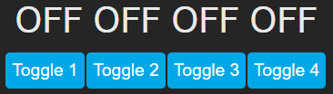
A state text and an on/off button are automatically created on the Web GUI and syncs with the pin state.
All Power features are supported including PowerOnState, PulseTime, Blink, SetOption0, ...
Usage~
Enabling USE_PCF8574_SENSOR adds a PCF8574-xx field into the JSON payload of the tele/topic/SENSOR message. The form of the message is:
{"Time":"2021-03-11T19:50:58+01:00","PCF8574-1":{"D0":1,"D1":1,"D2":1,"D3":1,"D4":0,"D5":0,"D6":0,"D7":0}}
As you can see, all pins are listed, including both inputs and outputs. The value reported is the digital level of the pin. If "Invert Ports" has been enabled, Power ON will be reported as 0 as the pin is at a LOW level.
As for any sensor published in the tele/topic/SENSOR message, it is possible to use Rules triggers such as:
ON tele-PCF8574-1#D0 DO something_with %value% ENDON
== can be used to compare to 0 or 1. See also change detection. PCF8574 inputs pins in the Web GUI~
Enabling USE_PCF8574_DISPLAYINPUT will add the state of PCF8574 inputs displayed as sensors in the Web GUI. Outputs are not represented here as they are already shown as Power.
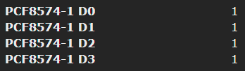
Value of pin is updated in almost "real-time".
Input Change Detection~
While reporting the pin level in SENSOR or on the GUI is interesting, it is even better to detect pin change. This is enabled by USE_PCF8574_MQTTINPUT. When this feature is enabled at build time, a test will be performed every 50ms to detect if an input pin has changed. In that case, Tasmota will publish on stat/topic/PCF8574_INP a JSON payload with the PCF8574 index and the pin level:
20:19:39.385 MQT: stat/topic/PCF8574_INP = {"Time":"2021-03-11T20:19:39+01:00","PCF8574-1_INP":{"D0":0}}
20:19:39.584 MQT: stat/topic/PCF8574_INP = {"Time":"2021-03-11T20:19:39+01:00","PCF8574-1_INP":{"D0":1}}
This can be caught in rules such as:
Implementing a Power push "Button":
ON PCF8574-1_INP#D0=0 DO Power2 toggle ENDON