PIR Motion Sensors
PIR motion sensors, albeit called sensors, are configured as switches in Tasmota since they basically report motion (1) or no motion (0) to the device.
Most PIR's are single wire and they require connecting to VCC, GND and one GPIO. In this guide we will use GPIO13 as the pin that the PIR output is connected to. See PIN Restrictions on which pins not to use.
In the simple case of wanting PIR activity to turn on a light/fan connected to the same device, you can use SwitchMode 13 (push to on), along with a PulseTime for the minimum on-period. Then you can skip the more detailed options on this page.
Tasmota Settings~
In Configuration -> Configure Module menu change GPIO13 to Switch1. 
If there already is a Switch1 simply choose the next in line. Same applies if you're connecting more than 1 PIR on a single device.
A configured PIR will not appear in the web UI in any form. To make it report like a sensor we need a rule that will send movement triggers to an MQTT topic.
SwitchMode1 1
SwitchTopic 0
Rule1 on Switch1#state=1 do publish stat/%topic%/PIR1 ON endon on Switch1#state=0 do Publish stat/%topic%/PIR1 OFF endon
Rule1 1
PIR1) and the message (ON/OFF) to whatever suits your needs. %topic% is the configured device topic. Look in console for motion detection messages [20:24:03] stat/%topic%/PIR1 ON to verify everything is working
optional: Before using rules configure any GPIO that doesn't have anything connected to it as Relay1.
This creates a dummy relay which is triggered by the PIR so you can see the changes in the web UI. This method is not recommended for daily use and should only be used for testing.
A more advanced example of rules with PIRs.
AM312~
AM312 works even on 3.3v instead of 5v (like HC-SR501) which makes it perfect for ESP8266 devices without a 5V line (like Sonoff Basic). It is also less prone to false triggers due to Wi-Fi interference.
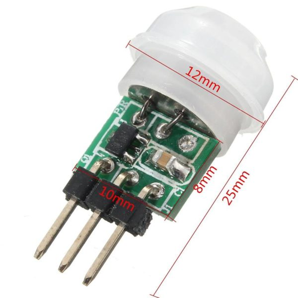
Pinout~

Pin marked VOUT is connected to a free GPIO pin on the device.
This PIR goes to off state after a few seconds so we need to use this rule instead of the one in the example.
Rule1 on Switch1#state=1 do Backlog Publish stat/%topic%/PIR1 ON; RuleTimer1 30 endon on Rules#Timer=1 do Publish stat/%topic%/PIR1 OFF endon
Another configuration option is to change Switchmode to 14 with Pulsetime of 130 (30 seconds on every time the AM312 is triggered)
Another use case as a hand wave switch.
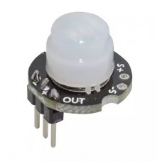
HC-SR501~

Pinout~

Configuration with HC-SR501 is easiest with Switchmode 1, since this module has a built-in trigger/delay potentiometers and the state remains ON during the trigger period.
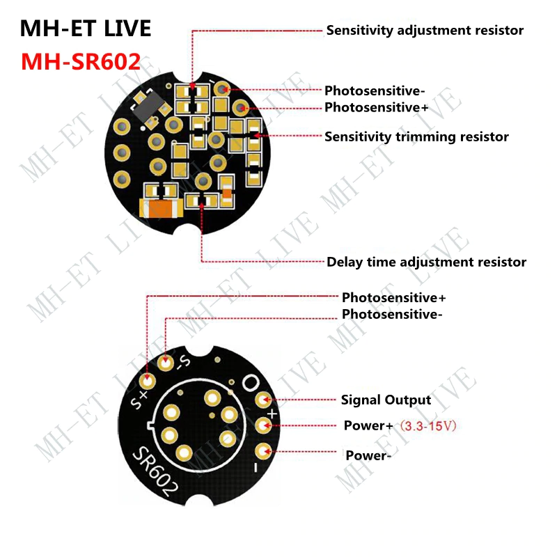
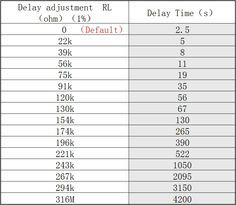
MH-SR602~
This is a very small version of a PIR that is able to modify the sensitivity and delay by soldering resistors.
With factory settings this PIR goes to off state after a few seconds so we need to use this rule instead of the one in the example.
Rule1 on Switch1#state=1 do Backlog Publish stat/%topic%/PIR1 ON; RuleTimer1 30 endon on Rules#Timer=1 do Publish stat/%topic%/PIR1 OFF endon
Pinout~
Panasonic EKMC1603111~
Set the data pin to Switch n for it to work.
Configuring Tasmota to for Home Assistant~
To make Home Assistant recognize your PIR sensor automatically, skip all previous steps, and execute the following steps to make Tasmota announce your PIR as a motion sensor.
- In Configuration -> Configure Module menu change your GPIO pin to
Switch2(or any other switch number). - Assuming you picked
Switch2in the previous step, run this command:
Backlog rule1 on switch2#state do publish stat/%topic%/MOTION %value% endon; rule1 1; switchmode2 1, so19 1
- Run this very-long command all at once:
rule2 on system#boot do publish2 homeassistant/binary_sensor/%topic%/config {
  "name": "Motion Sensor",
  "state_topic": "stat/%topic%/MOTION",
  "payload_on": 1,
  "availability_topic": "tele/%topic%/LWT",
  "payload_available": "Online",
  "payload_not_available": "Offline",
  "device_class": "motion",
  "force_update": true,
  "off_delay": 30,
  "unique_id": "%deviceid%_motion",
  "device": {
    "identifiers": [
      "%deviceid%"
    ]
  }
} endon
- Run the following two commands to enable the rule, and then restart the device:
Rule2 1
Restart 1
Note that this configuration, much like the rest of the examples on this page, don't show the PIR sensor's state on the home screen of Tasmota.