PZEM-0xx power monitor~
PZEM is a dedicated separate energy monitor, device calibration in Tasmota is not necessary, the PZEM devices are precisely factory-calibrated.
PZEM-004~


The PZEM-004T together with a Sonoff Basic provide a good clamp on energy monitor.
Parts needed~
- Sonoff Basic
- PZEM-004T
- Resistor 1k
- Enclosure
- Power cable
Preparation~
Install Tasmota on the Sonoff Basic and confirm it is functional before connecting the PZEM-004T to its serial interface.
Hardware connections~
As the PZEM-004T RX optocoupler series resistor (1K ohm, R15 for v.1 .0 and R8 for v.3.0 ) is designed for 5V, that resistor value had to be reduced in order to achieve the current for driving the RX optocoupler diode. This can be accomplished by soldering a 1k resistor between the joints shown below (modification works for version v.1.0 and v.3.0). The resistor has to be connected between VDD (5V/3.3V) terminal and the RX opto terminal 1.
PZEM-004T v.1.0

PZEM-004T v.3.0 
It can be used a SMD resistor 102 or 1001 (1K) soldered near/parallel with R8 or a normal resistor (THT) similar to that used on the image of v.1.0 The resistor is placed in different place on v.3.0 because the optocouplers RX and TX are reversed compared to v.1.0
Connect the serial interface of the Sonoff Basic with the serial interface of the PZEM-004T. See pictures regarding used colors and connections.
- 3V3/5V Red
- Rx Yellow
- Tx Green
- Gnd Grey

(Image re-used from https://www.instructables.com/id/Use-Homie-Firmware-to-Drive-Sonoff-Switch-Module-E/ Thanks @amayii0)
If you need 5V you can use directly from Sonoff (for something else) but do not connect to PZEM logic because this will result in a big flash (kaboom!, the sonoff LIVE line may reach the PZEM NEUTRAL or viceversa). Using 5V from Sonoff for PZEM TTL port is safe but the resistor mod explained above must be undone and another mod is needed for dropping the PZEM TX line from 5V to 3.3V. So, the simplest way is to use 3.3V from Sonoff to 5V TTL terminal of the PZEM and the resistor mod explained in the above images.
Cut the power cable in two and connect the input wires to both Sonoff Basic and PZEM-004T. Route one of the power output wires through the PZEM-004T core and connect the output wires to the Sonoff Basic output.
As most parts are connected to high voltage AC it is recommended to fit the hardware in a solid enclosure.
Software configuration~
Configure the GPIO's for hardware serial connection as shown below.
IMPORTANT: If using the connections as following, the communication works in all cores due to TASMOTA using hardware serial. If the user wants to use other GPIOs for communication, TASMOTA will emulate a serial interface using software serial. This feature does not work using core 2.3.0 due to insufficient RAM. To use the software serial feature, you must use a core version of 2.4.2 or greater.
Device Template
PZEM-004T version prior to V3:
{"NAME":"HW-655 PZEM","GPIO":[0,62,0,63,0,0,0,0,0,0,0,0,0],"FLAG":0,"BASE":1}
PZEM-004T version V3~
{"NAME":"HW-655 PZEM","GPIO":[0,62,0,98,0,0,0,0,0,0,0,0,0],"FLAG":0,"BASE":1}

The PZEM-004T together with a HW-655 Relay provide a good clamp-on energy monitor for a 240V clothes dryer.
Parts needed~
- Circuit Box
- 3-prong Dryer Electrical Cord (Note - some households use a 4-prong plug)
- 3-prong Dryer Receptacle (Note - some households use a 4-prong plug)
- PZEM-004T
- HW-655 w/ ESP-01
- ESHION SPSD-5S AC-DC 5V Buck Converter
- 4-pin Serial Connector
- DuPont Connectors & 22 AWG wire
Preparation~
Install Tasmota on the ESP-01 and confirm it is functional before connecting the PZEM-004T to its serial interface. Use of pins other that the default hardware serial GPIO (01 & 03) in order for TASMOTA to emulate a serial interface using software serial.
Hardware connections~

Connect the serial interface of the HW-655 with the serial interface of the PZEM-004T.

As most parts are connected to high voltage AC it is recommended to fit the hardware in a solid enclosure.

Software configuration~
Device Template
PZEM-004T version prior to V3:
{"NAME":"HW-655 PZEM","GPIO":[0,62,0,63,0,0,0,0,0,0,0,0,0],"FLAG":0,"BASE":18}
PZEM-004T version V3~
{"NAME":"HW-655 PZEM","GPIO":[0,62,0,98,0,0,0,0,0,0,0,0,0],"FLAG":0,"BASE":18}
Use the module template to configure the GPIO's for hardware serial connection.
IMPORTANT: If using the connections as following, the communication works in all cores due to TASMOTA using hardware serial. If the user wants to use other GPIOs for communication, TASMOTA will emulate a serial interface using software serial. This feature does not work using core 2.3.0 due to insufficient RAM. To use the software serial feature, you must use a core version of 2.4.2 or greater.
Connected Power Meter using PZEM-004T, Wemos D1 Mini and a 1602 I2C display~
Parts needed~
- Wemos D1 Mini
- PZEM-004T
- 1kOhm Resistor (optional - see alternate wiring)
- Enclosure
- 5V buck converter power supply (search for "700ma 3.5w 5v" on usual stores...)
- I2C 1602 LCD Display (I had issues with green one, I2C address 0x3F, while no problems with blue ones, address 0x27)
- Mains Power cable
- Mammuth Clamps
Preparation~
You need to compile your own Tasmota firmware as none of the pre-compiled binaries have support for display and PZEM module.
Set up your preferred IDE as described in wiki
Enable IDE to Use Custom Settings~
Create user_config_override.h in the tasmota folder and paste the contents of this sample configuration file.
PlatformIO~
- Rename platformio_override_sample.ini. to platformio_override.ini
- Enter
platformio run -e <variant-name>
Examples: platformio run -e tasmota-sensorsplatformio run -e tasmota-DE
Tasmota Parameter Configuration~
Device Template
PZEM-004T version prior to V3:
{"NAME":"HW-655 PZEM","GPIO":[0,62,0,63,6,5,0,0,0,0,0,0,0],"FLAG":0,"BASE":18}
PZEM-004T version V3~
{"NAME":"HW-655 PZEM","GPIO":[0,62,0,98,6,5,0,0,0,0,0,0,0],"FLAG":0,"BASE":18}
- use
I2CScanto detect your device address - use
DeviceAddress XXX(where XXX is the decimal converted address found) to set the I2C address - set
TelePeriod 10to have the display refresh every 10 seconds (you can't go under this value) - set
DisplayModel 1, andDisplayMode 0 - finally, add a Rule to display values (I choose these):
Rule1 ON Tele-ENERGY#Power DO DisplayText [z] [x1y0]%value%W ENDON ON Tele-ENERGY#Today DO DisplayText [x8y0]%value%Wh ENDON ON Tele-ENERGY#Voltage DO DisplayText [x1y1]%value%V ENDON ON Tele-ENERGY#Current DO DisplayText [x8y1]%value%A ENDON - remember to enable the rule, with
Rule1 1
Images and Wiring diagram~
DANGER - MAINS VOLTAGE. Be sure to crimp connectors and use heat-shrinking tube wherever possible/needed, and tightly secure any screw.

How it looks, from web GUI:

How it looks, from enclosure:

You can set the contrast using the little trimmer/pot on back of the display. I cut a bit of the corners from the display to have it flush with border, and used two hexagonal plastic standoffs with nuts and bolts to secure it to transparent top.
Mains IN, mains OUT, all sealed:

Wiring Diagram: * Check images below for more information about the 1kOhm resistor needed to use 3.3V instead of 5V for the PZEM-004T serial connection.
PZEM-004T v.1.0
PZEM-004T v.3.0

Calibration~
Per Theo - As the PZEM is a dedicated energy monitor, device calibration in TASMOTA is currently not supported.
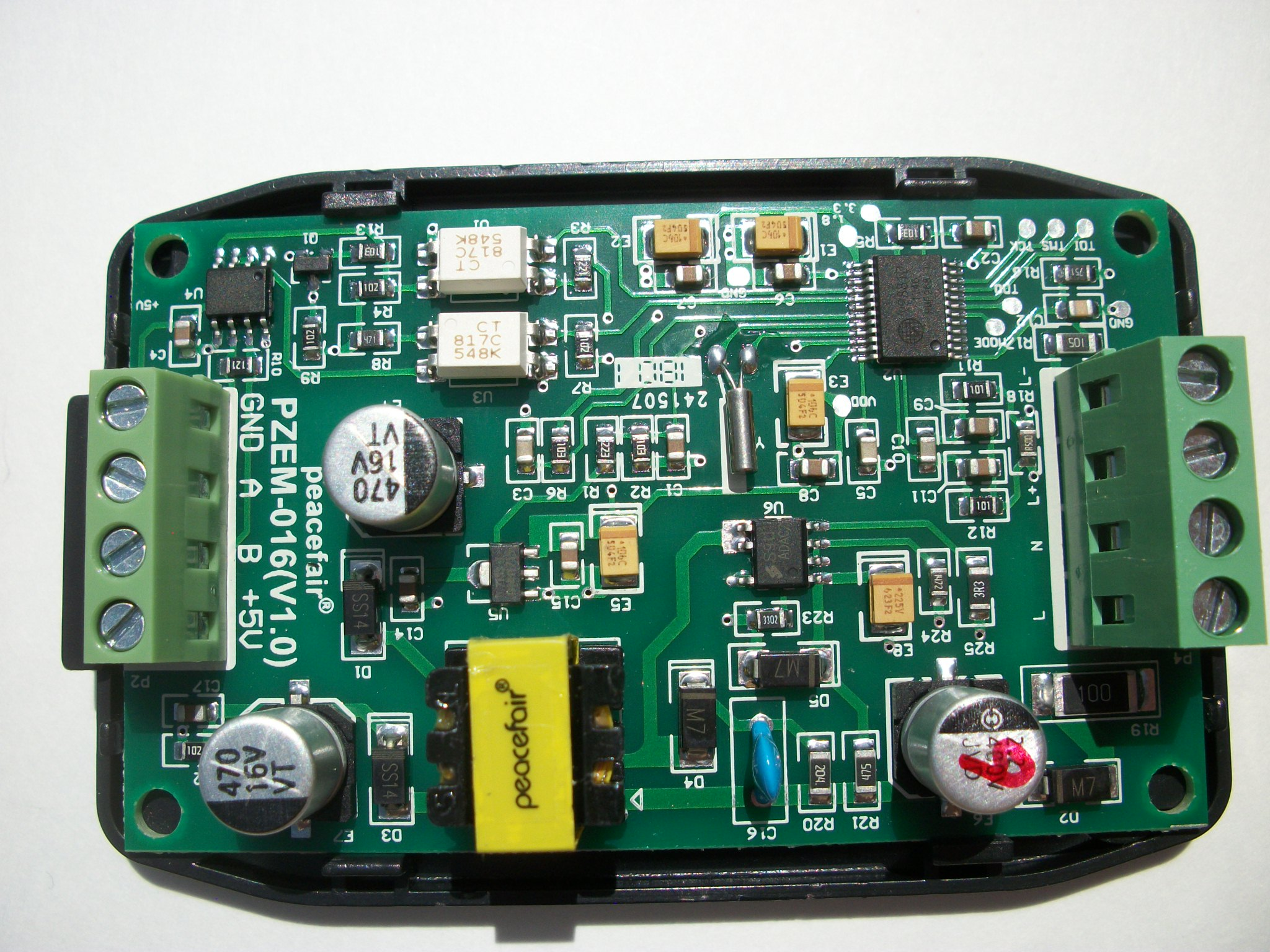
PZEM-016~

DO NOT PERFORM THIS MODIFICATION WITHOUT REMOVING POWER FROM THE PZEM FIRST!
Note: the PZEM-016 TTL output is at 5V signal levels. There are varying schools of thought on whether the ESP82xx has 5V tolerant GPIO. You may want to use a level shifter for the serial communications signals to bring them to the recommended 3.3V.
PZEM-016 modules can be converted from RS485 to TTL serial level devices by simply removing the internal MAX485 chip and adding two internal jumper wires. This will bring the serial port connections out via the four-pin terminal block. Pin A is now TTL serial out (Tx) and pin B TTL serial in (Rx). The modification retains the optical isolation used by the PZEM for safety to ensure no high voltages on the outputs.


You can use a voltage level shifter to power the ESP82xx from the PZEM-016 module's 5V power. This may also require a 470uf 35V capacitor across the 5V line to work reliably. 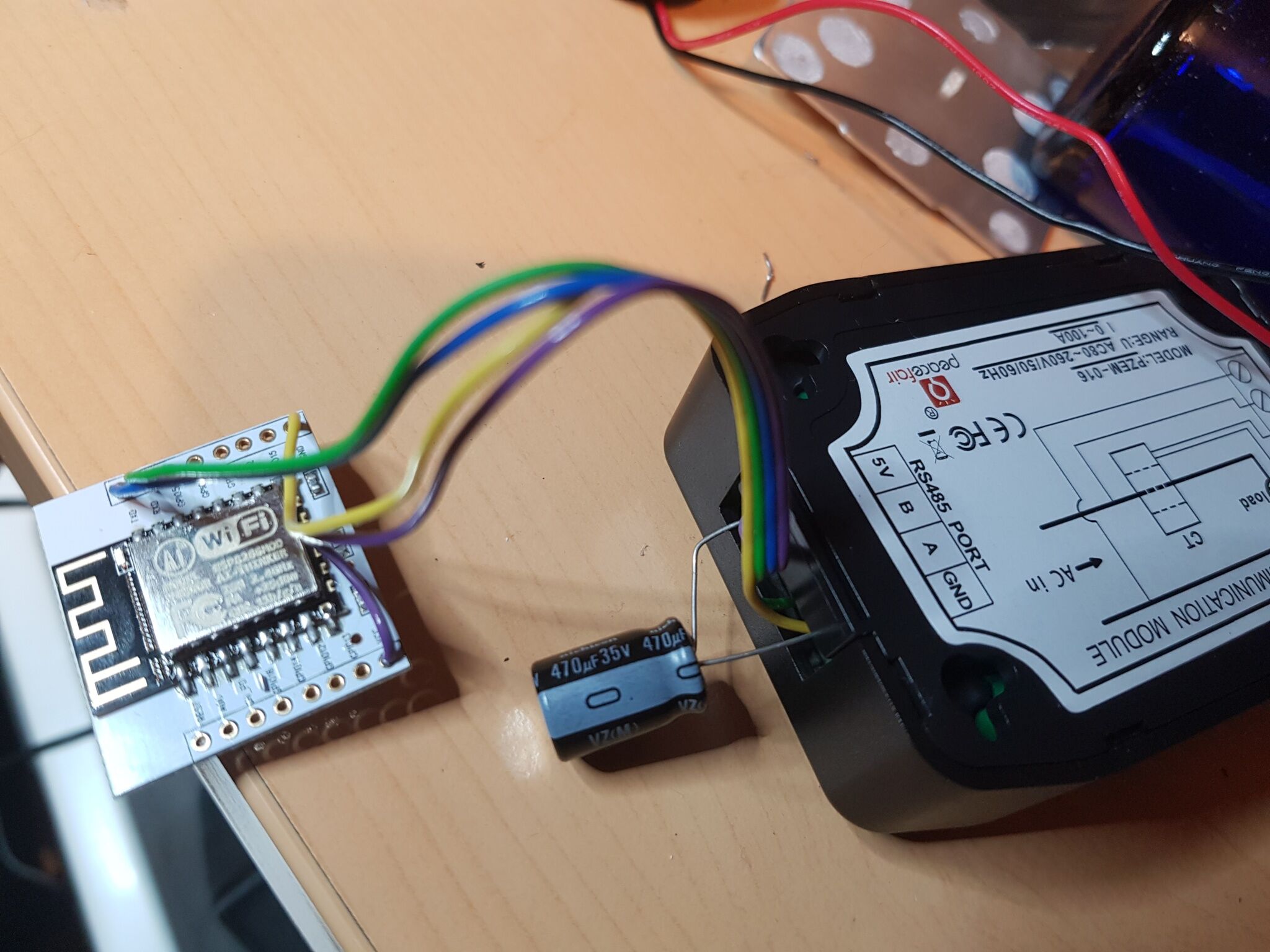
Tasmota Configuration~
It is recommended to use GPIO1/GPIO3 or GPIO13/GPIO15 for the most reliable serial communications. When using other GPIOs software serial will be activated and used.
| GPIO | Component | PZEM |
|---|---|---|
| 1 | PZEM0XX Tx (62) | Pin B |
| 3 | PZEM016 Rx (98) | Pin A |