SolaX Power - Single phase string inverter X1~
This feature is not included in precompiled binaries
When compiling your build add the following to user_config_override.h:
#ifndef USE_SOLAX_X1
#define USE_SOLAX_X1
#endif
There are additional #define compiler directive parameters which can be used, if they are necessary for your setup.
Set an other serial speed than the default value of 9600:
#undef  SOLAXX1_SPEED
#define SOLAXX1_SPEED  9600
#ifndef SOLAXX1_PV2
#define SOLAXX1_PV2
#endif
ReadConfig command to save about 3k1 bytes of code. To do this, simply remove the compiler directive: #define SOLAXX1_READCONFIG
#ifndef USE_ENERGY_SENSOR
#define USE_ENERGY_SENSOR
#endif
General~
This module reads runtime values from a Solax X1 device via RS485 Modbus interface and publishes them to MQTT.
The communication of this module is based on the description of the communication protocol version 1.8.
Wiring~
To connect the inverter to the Tasmota-device, you have to use a breakout board to adapt the RS485 interface of the inverter to serial interface of the ESP.
Breakout boards~
There are many RS485-to-TTL modules, aka breakout boards, available. They may work or not. You should have attention on the operation voltage. The ESP-devices work with 3 volts. Because of that be careful experimenting with 5 volts. In the best case nothing works. In the worst case it will destroy your ESP or breakout board. Here are two examples of tested breakout boards. Recommended is a board with a SP3485 chip, because it is designed for operating at 3 volts.
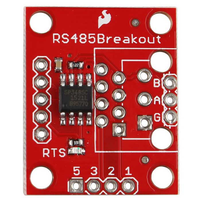
SP3485~
The SP3485 breakout board is specially made to work with only 3 volts. It has a separate RTS-pin and works with a voltage from 3 to 5 volts.
HW-0519~
The HW-0519 breakout board does not need a separate RTS-pin, because it automatically switches between sending and receiving. The recommended voltage is 5 volts, but it should also work with 3 volts.

ESP ⬌ breakout board~
The RX-, TX- and RTS- (if needed) lines have to be connected to the ESP matching the module configuration.
| ESP | SP3485 | HW-0519 |
|---|---|---|
| 3.3V | 3-5V | VCC |
| GND | GND | GND |
| RX | TX-O | RXD |
| TX | RX-I | TXD |
| RTS | RTS | - |
Breakout board ⬌ inverter~
The RS485 interface is a 2-wire-connection. The wires are called A+ and B-. The big advantage of the interface is, beside of needing only two wires, that it can reach a length up to 1200 meters. The inverter has a RJ45-jack, where the interface is accessible. Please consult the manual of your inverter where it is located.
Tip: You can use an ethernet cable and cut off one connector. The RS485 interface uses the blue wire pair.
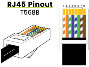
| Breakout board | RJ45 inverter | Wire color (T568B) |
|---|---|---|
| A (+) | Pin 4 | blue |
| B (-) | Pin 5 | blue-white |
| G / Ground | Pin 7 | brown-white |
Info
In many cases two wires are enough to keep it working without errors. When your environment has electrical interferences or your cable is quiet long, you should use a third wire to establish a common signal reference. This wire has to be connected to the Ground pins.
Configuration~
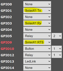
You have to configure the module or the template. Select SolaxX1 Tx and SolaxX1 Rx for the RS485 communication. If you have a breakout board which needs the RTS line, you must also select SolaxX1 RTS.
Operation~
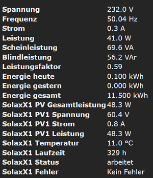
Result~
When every thing works you will see the current data on the main page. They are also provided via MQTT.
Tips
- To send a MQTT telemetry message immediately on every change of power, you can set a
PowerDeltavalue.
E.g.PowerDelta 101for every change of at least 1 W. - Set
SetOption72to1for displaying the value of total energy reported from the inverter.
Console commands~
There are two special console commands for the X1 converter:
EnergyConfig ReadIDinfo reads and displays ID-data from the inverter
EnergyConfig ReadConfig reads and displays the configuration from the inverter
Inverter status~
The inverter status field represents the value reported by the inverter, when the inverter is sending data. In the case when no data is received, it will be display off. As the converter is only working, when the sun is shining, you will see off normally at night or too low light.
Tip
When the inverter is working and off is displayed, so you have to check your hard- and software setup.
Meter Mode~
The Meter Mode can be used to easily build a zero injection solution. When the export control is enabled in the inverter settings, it requests the momentary grid consumption from an attached meter. This driver emulates the meter and reports back the requested values. Based on this values and the integrated export control algorithm, the inverter can limit the output to only be sufficient to the load, so as to achieve zero injection to the grid.
The grid load consumption can be measured by any device, like a meter, smart meter, etc. and transmitted to the driver. Please consult the commands.
The driver automatically detects when the inverter requests the meter mode. Only one mode is possilbe at the same time.
Tip
To avoid problems, be sure the "normal" mode works completely flawlessly.
Enable export control~
Setting up the inverters export control function can be done via LCD. As an example, the steps are as follows:
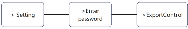
For more information have a look at the user manual of the inverter.
Commands (Meter Mode)~
The meter values can be communicated to the driver via this commands:
EnergyConfig MeterPower current imported or exported power in W (required)
EnergyConfig MeterImport imported energy in kWh to be displayed on the inverter (optional)
EnergyConfig MeterExport exported energy in kWh to be displayed on the inverter (optional)
A good way for operation is to subscribe to the (smart) meter MQTT topics directly. Therefore compile with #define SUPPORT_MQTT_EVENT.
A sample rule subscribing to values of the SML driver can look like this:
Rule1
ON mqtt#connected DO Subscribe PwrEvt, MT175/tele/SENSOR ENDON
ON Event#PwrEvt#SML#Power_all DO EnergyConfig MeterPower %value% ENDON
ON Event#PwrEvt#SML#Total_in DO EnergyConfig MeterImport %value% ENDON
ON Event#PwrEvt#SML#Total_out DO EnergyConfig MeterExport %value% ENDON