TM1637, TM1638 and MAX7219 Seven-Segment Display~
This feature is included only in tasmota*-display.bin precompiled binaries
When compiling your build add the following to user_config_override.h:
#ifndef USE_DISPLAY
#define USE_DISPLAY
#endif

#ifndef USE_DISPLAY_TM1637
#define USE_DISPLAY_TM1637
#endif
#ifndef USE_DISPLAY_MAX7219
#define USE_DISPLAY_MAX7219
#endif
| TM1637 | TM1638 | MAX7219 |
|---|---|---|
 | 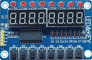 | 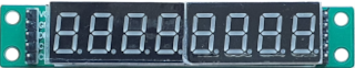 |
The TM1637, TM1638 and MAX7219 display modules are small (~ 10mm high digits) 7-segment, LED-based display units with 4/6 digits (TM1637), 8 digits and 8 digits (TM1638 and MAX7219) respectively. They use a two-wire (TM1637) or three-wire (TM1638 and MAX7219) I2C-like (but not exactly) protocol for communication with MCUs like the ESP8266 / ESP32 / Arduino etc.,
These modules are a great way to add a simple numeric display to any MCU project.
(In case a 8x8 dot matrix module is connected to the MAX7219 see: Support of MAX7219 for 8x8 LED dot matrix)
Features~
The Tasmota support for these modules can --
- display Numbers and Floats with control over position and leading zeros.
- display basic Text, for example, sending the text
22.5^will display:

- display Raw segments.
- display Level, like a bar graph
- display Scrolling text
- display a Clock in 12 hr and 24 hr format
- set Brightness (8 levels) and Clear the display.
Configuration~
Wiring~
The TM1637 module needs to be connected to two GPIO pins and a 3.3V-5V power supply.
| TM1637 | ESP based module |
|---|---|
| CLK | GPIOx |
| DIO | GPIOy |
| VCC | 3.3V (e.g., ESP-01) or 5V (e.g., Wemos D1 Mini) |
| GND | GND |
The TM1638 module needs to be connected to three GPIO pins and a 5V power supply.
| TM1638 | ESP based module |
|---|---|
| CLK | GPIOx |
| DIO | GPIOy |
| STB | GPIOz |
| VCC | 5V |
| GND | GND |
The MAX7219 module needs to be connected to three GPIO pins and a 5V power supply.
| MAX7219 | ESP based module |
|---|---|
| CLK | GPIOx |
| DIN | GPIOy |
| CS | GPIOz |
| VCC | 5V |
| GND | GND |
Tasmota Settings~
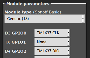
In Tasmota's Configuration -> Configure Module page, assign:
For TM1637
GPIOxtoTM1637 CLKGPIOytoTM1637 DIO
For TM1638
GPIOxtoTM1638 CLKGPIOytoTM1638 DIOGPIOztoTM1638 STB
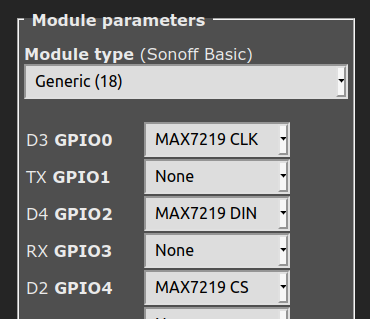
For MAX7219
GPIOxtoMAX7219 CLKGPIOytoMAX7219 DINGPIOztoMAX7219 CS
For example, if x=0 and y=2, z=4 then the module configuration would look like the following:
TM1637
TM1638
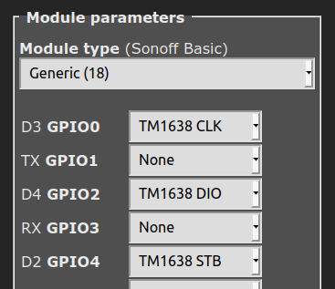
MAX7219
Initial Setup~
The power toggle button in webUI turns the display on or off. However, if there are additional relays defined, resulting in multiple power toggle buttons in WebUI, display power will create and map to the last button. Thus, it is necessary to ensure that relays are numbered from 1, otherwise a conflict will occur with the display power.
In the console, turn ON the display with the command Power 1.
DisplayModel~
Once the GPIO configuration is saved and the ESP8266 / ESP32 module restarts, set the Display Model to 15 using the command:
DisplayModel 15
DisplayWidth~
If you have a TM1637 with 6 digits, set the number of digits using the command:
DisplayWidth 6
DisplayType~
The 6-digit TM1637 has 2 known variants with different hardware wiring for the digit ordering.
You can switch between these two variants with the following commands:
DisplayType 0 - Use this for the Type 0 variant, with wiring similar to the TM1637 4-digit modules
DisplayType 1 - Use this for the Type 1 variant, with a different wiring that causes the text 123456 to appear as 321654
After the ESP8266/ESP32 module restarts again, the display module is ready to accept commands.
DisplayModes~
DisplayModes 0..3 are supported. The firmware default is DisplayMode 1.
To use the Seven-Segment specific Display- commands described below, set the DisplayMode to 0 with:
DisplayMode 0
DisplayDimmer~
The brightness of the display can be set using the DisplayDimmer command.
DisplayDimmer 0..100 maps the brightness value to 8 steps from 0..7
For a minimum brightness, make sure this value is at least about 13
7-Segment specific Commands~
The Display- commands listed below can be used from the Tasmota web-console, MQTT, and from Tasmota Rules
TM1638 leds and buttons~
In order to use the TM1638 leds and buttons, you must self-compile tasmota with the following in your user_config_override.h:
#define USE_DISPLAY
#define USE_DISPLAY_TM1637

#define USE_TM1638 // Add support for TM1638 switches copying Switch1 .. Switch8 (+1k code)
// #define TM1638_USE_AS_BUTTON // Add support for buttons
#define TM1638_USE_AS_SWITCH // Add support for switches (default)
#define TM1638_MAX_DISPLAYS 8 // Add support for power control 8 displays
#define TM1638_MAX_KEYS 8 // Add support for 8 keys
#define TM1638_MAX_LEDS 8 // Add support for 8 leds
This will define the buttons as Switches. If you want to use them as Buttons, invert the comments on the lines:
#define TM1638_USE_AS_BUTTON // Add support for buttons
//#define TM1638_USE_AS_SWITCH // Add support for switches (default)
The 8 leds will be created as Relays. If no other relays are defined, they will start as Relay1 up to Relay8. A 9th relay is assigned to the 7-segment display.
The 8 buttons will be created by default as Switches with all the features of switches including debouncing and all Switchmodes.
Alternatively, using #define TM1638_USE_AS_BUTTON they would be created as Buttons fully equivalent to a native Tasmota Button on a GPIO.
In all cases, leds, switches or buttons index will be assigned after native relays, switches or buttons get assigned. Other drivers providing relays, buttons or switchs initialized before TM1368 will be also get index assigned before TM1638. So actual indexes may depends on what other GPIO/drivers are configured on your system.
See rule sample below.
Commands and Usage~
| Console/MQTT Commands | Description | values |
|---|---|---|
| DisplayClear | Clears the display | |
| DisplayNumber | Clears and then displays number without decimal. command e.g., "DisplayNumber 1234". Control position, leading zeros, and length. position can be 0 (left-most) to NUM_DIGITS-1 (right-most), leading zeros can be 1 or 0 (default), length can be 1 to NUM_DIGITS (4 or 6). Command example: DisplayNumber 12, 1, 1, 3 This will display: | num [, position[, leading_zeros[, length]]] |
| DisplayNumberNC | Display integer number as above, but without clearing first. e.g., "DisplayNumberNC 1234". Usage is same as above. | same as above |
| DisplayFloat | Clears and then displays float (with decimal point) command e.g., "DisplayFloat 12.34". Control position, precision, length and alignment. position can be 0 (left-most) to NUM_DIGITS-1 (right-most), precision can be 0 to NUM_DIGITS (default), length can be 1 to NUM_DIGITS (4 or 6). alignment can be 0 for left and 1 for right. Command example: DisplayFloat 2.48, 1, 1, 2 This will display: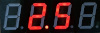 | num[, position[, precision[, length [, alignment]]]] |
| DisplayFloatNC | Displays float (with decimal point) as above, but without clearing first. command e.g., "DisplayFloatNC 12.34" | same as above |
| DisplayRaw | Takes up to NUM_DIGITS comma-separated integers (0-255) and displays raw segments. Each number represents a 7-segment digit. Each 8-bit number represents individual segments of a digit. Segment a=1, b=2, c=4, d=8, e=16, f=32, g=64 and h (decimal point)=128. To turn on all segments, the number would be 1+2+4+8+16+32+64+128 = 255 For example, the command DisplayRaw 0, 2, 255, 255 would display: | position, length, num1 [, num2[, num3[, num4[, ...up to NUM_DIGITS numbers]]...] |
| DisplayText | Clears and then displays basic text. Command e.g., DisplayText a.b12 Control length and position of the displayed text. length can be 1 to NUM_DIGITS , position can be 0 (left-most) to NUM_DIGITS-1 (right-most) A caret( ^) symbol in the text input is displayed as the degrees(°) symbol. This is useful for displaying Temperature (or angle)! For example, the command DisplayText 22.5^ will display: | text[, position[, length]] |
| DisplayTextNC | Displays text without first clearing the display. Usage is same as above. | same as above |
| DisplayScrollText | Displays scrolling text, up to 50 characters. If num_iterations is not specified, it scrolls indefinitely, until another Display- command is issued. Optionally, specifying num_iterations causes the scrolling to stop after the specified number of iterations.Command examples: DisplayScrollText tasmota is awesome -- causes indefinite scrollingDisplayScrollText tasmota is awesome, 5 -- causes scrolling to stop after 5 iterations | text [, num_iterations] |
| DisplayScrollDelay | Sets the speed of text scroll. Smaller delay = faster scrolling. | 0 to 15 |
| DisplayLevel | Display a horizontal bar graph. Command e.g., DisplayLevel 50 will display: | 0 to 100 |
| DisplayClock | Displays a clock. DisplayClock 1 displays a clock in 12-hour format. DisplayClock 2 displays a clock in 24-hour format. DisplayClock 0 turns off the clock and clears the display | 1 or 2 or 0 |
Usage in Rules~
All the above commands can be used in Tasmota Rules, as usual.
For example, a simple digital thermometer can be implemented by connecting a DHT22 Temperature-Humidity Sensor and a TM1637 to a Wemos D1 Mini, and writing a Rule like the following:
Rule1
ON Tele-AM2301#Temperature DO DisplayText %value%^ ENDON
Rule1
on sht3x#Temperature!=%var1% do backlog displaytextnc %value%^;var1 %value% endon on sht3x#Humidity!=%var2% do backlog displaytextnc %value%h,4;var2 %value% endon on system#init do power 1 endon
TM1638 in rules~
As the leds and buttons are fully equivalent to Relays and Buttons/Switches, they can be used in rules in exactly the same way as native Relay/Power, Buttons/Switches.
Here is a little ruleset which implement a 8-digit code entry (using only digit 1 to 8).
At start Time is displayed (DisplayMode 1) but as soon as you type in the 1st key, it starts the entry mode. After each digit entry the user has up to 5 seconds to enter the next digit. It (s)he fails, the state machine is reset and the display reverts showing Time.
Once all 8 digits are entered, the resulting string is stored in var3 as a text message.
This is only a sample which can be adapted for example to send the code through MQTT.
DisplayModel 15
DisplayWidth 8

rule1
  on system#init do event reset endon
  on event#reset do backlog ruletimer1 0; displaymode 1; var1 1; var2 " endon
  on button1#state do event key=1 endon
  on button2#state do event key=2 endon
  on button3#state do event key=3 endon
  on button4#state do event key=4 endon
  on button5#state do event key=5 endon
  on button6#state do event key=6 endon
  on button7#state do event key=7 endon
  on button8#state do event key=8 endon
  on event#key do backlog var2 %var2%%value%; displaymode 0; displaytext %var2%%value%; ruletimer1 5; add1 1 endon
  on rules#timer=1 do event reset endon
  on var1#state==9 do backlog ruletimer1 5; var3 The Code is %var2% endon

rule1 1
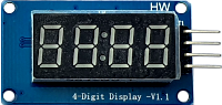
TM1637 Images~
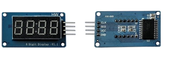
The TM1637 4-digit module (front and back)
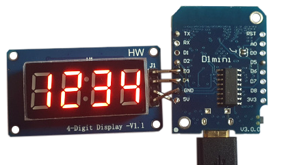
TM1637 4-digit module with Wemos D1 Mini