Thermostat
This feature is not included in precompiled binaries
When compiling your build add the following to user_config_override.h:
#define USE_THERMOSTAT                           // Add support for Thermostat
    #define THERMOSTAT_CONTROLLER_OUTPUTS         1         // Number of outputs to be controlled independently
    #define THERMOSTAT_SENSOR_NAME                "DS18B20" // Name of the local sensor to be used
    #define THERMOSTAT_SENSOR_NUMBER              1         // Number of local sensors to be used
    #define THERMOSTAT_RELAY_NUMBER               1         // Default output relay number for the first controller (+i for following ones)
    #define THERMOSTAT_SWITCH_NUMBER              1         // Default input switch number for the first controller (+i for following ones)
    #define THERMOSTAT_TIME_ALLOW_RAMPUP          300       // Default time after last target update to allow ramp-up controller phase in minutes
    #define THERMOSTAT_TIME_RAMPUP_MAX            960       // Default time maximum ramp-up controller duration in minutes
    #define THERMOSTAT_TIME_RAMPUP_CYCLE          30        // Default time ramp-up cycle in minutes
    #define THERMOSTAT_TIME_SENS_LOST             30        // Maximum time w/o sensor update to set it as lost in minutes
    #define THERMOSTAT_TEMP_SENS_NUMBER           1         // Default temperature sensor number
    #define THERMOSTAT_TIME_MANUAL_TO_AUTO        60        // Default time without input switch active to change from manual to automatic in minutes
    #define THERMOSTAT_TIME_RESET                 12000     // Default reset time of the PI controller in seconds
    #define THERMOSTAT_TIME_PI_CYCLE              30        // Default cycle time for the thermostat controller in minutes
    #define THERMOSTAT_TIME_MAX_ACTION            20        // Default maximum thermostat time per cycle in minutes
    #define THERMOSTAT_TIME_MIN_ACTION            4         // Default minimum thermostat time per cycle in minutes
    #define THERMOSTAT_TIME_MIN_TURNOFF_ACTION    3         // Default minimum turnoff time in minutes, below it the thermostat will be held on
    #define THERMOSTAT_PROP_BAND                  4         // Default proportional band of the PI controller in degrees celsius
    #define THERMOSTAT_TEMP_RESET_ANTI_WINDUP     8         // Default range where reset antiwindup is disabled, in tenths of degrees celsius
    #define THERMOSTAT_TEMP_HYSTERESIS            1         // Default range hysteresis for temperature PI controller, in tenths of degrees celsius
    #define THERMOSTAT_TEMP_FROST_PROTECT         40        // Default minimum temperature for frost protection, in tenths of degrees celsius
    #define THERMOSTAT_TEMP_RAMPUP_DELTA_IN       4         // Default minimum delta temperature to target to get into rampup mode, in tenths of degrees celsius
    #define THERMOSTAT_TEMP_RAMPUP_DELTA_OUT      2         // Default minimum delta temperature to target to get out of the rampup mode, in tenths of degrees celsius
    #define THERMOSTAT_TEMP_PI_RAMPUP_ACC_E       200       // Default accumulated error when switching from ramp-up controller to PI in hundredths of degrees celsius
    #define THERMOSTAT_TIME_OUTPUT_DELAY          180       // Default output delay between state change and real actuation event (f.i. valve open/closed)
    #define THERMOSTAT_TEMP_INIT                  180       // Default init target temperature for the thermostat controller
    #define THERMOSTAT_TIME_MAX_OUTPUT_INCONSIST  3         // Default maximum time where the input and the output shall differ (for diagnostic) in minutes
    #define THERMOSTAT_TIME_MAX_AUTOTUNE          21600     // Maximum time for the PI autotune function to complete in seconds
    #define THERMOSTAT_DUTYCYCLE_AUTOTUNE         35        // Default duty cycle (in % over PI cycle time) for the step response of the autotune PI function
    #define THERMOSTAT_PEAKNUMBER_AUTOTUNE        8         // Default number of peak temperatures (max or min) to be used for the autotune PI function
    #define THERMOSTAT_TEMP_BAND_NO_PEAK_DET      1         // Default temperature band in thenths of degrees celsius within no peak will be detected
    #define THERMOSTAT_TIME_STD_DEV_PEAK_DET_OK   10        // Default standard deviation in minutes of the oscillation periods within the peak detection is successful
Control over heating and cooling as a true HVAC unit
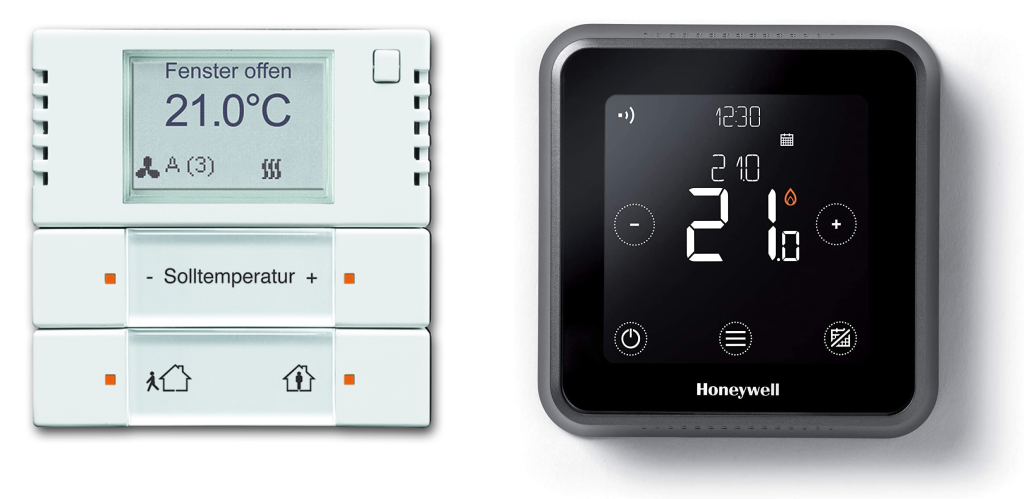
The Thermostat driver allows a Tasmota device to follow control heating/cooling strategies to reach the desired setpoint. In order to accomplish this it must be provided with the present temperature either via MQTT or a locally connected sensor. The thermostat offers similar functions as the feature rich commercial models found below:
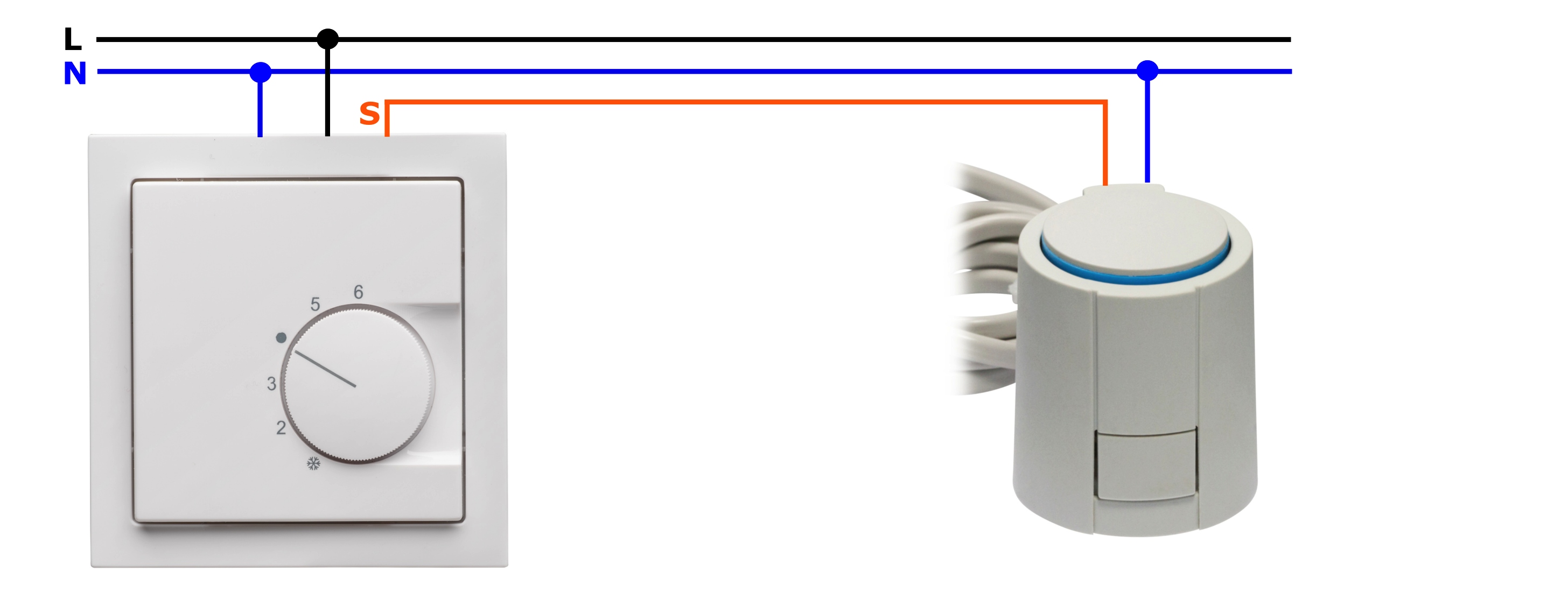
Typical setup: Heating floor system~
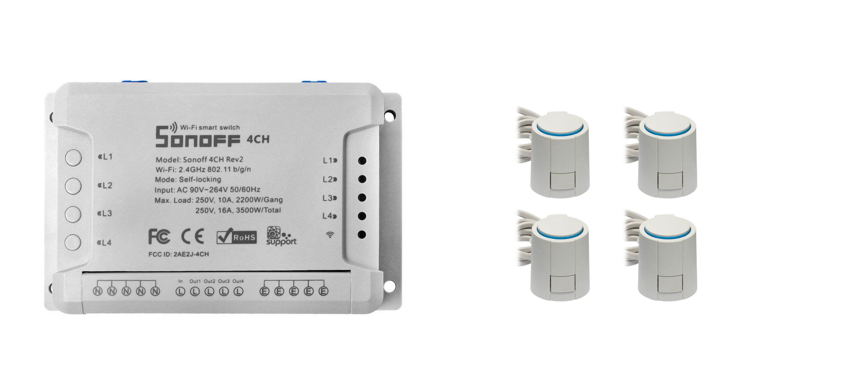
A typical setup for heating room systems can be found in the picture below. A conventional room thermostat is connected to a heating floor valve actuator, both running at AC voltage (e.g., 220V). The thermostat is connected to neutral as well as to the phase, the actuator to the same neutral connection of the thermostat and to its actuation signal. The actuation signal will switch between the neutral voltage (actuation Off) and the phase voltage (actuation On).
Conventional room thermostats offer nowadays either 2 point control with hysteresis or a more advanced PI (Proportional-Integral) control. While the result of the PI control is an analog value, in order to control a digital devices such as a relay, it is typically transformed into a PWM signal with a pre-defined period and a variable duty cycle.
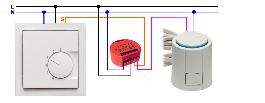
Use of tasmota switch to bypass an existing wall thermostat~
A tasmota switch can be installed in conjunction with an existing wall thermostat. The advantage of this setup is that the thermostat driver offers the possibility of following the output of the existing wall thermostat or of acting autonomously. This setup allows a seamless integration with existing wall thermostats and gives the user the freedom to still use them.
Below you can find an example of a Shelly switch bypassing a wall thermostat:
Configuration for standalone application or bypass of existing wall thermostat~
The driver by default ignores the input switch states, making it completely standalone (independently of any existing wall thermostat). The bypass function is specially useful to allow the user to bypass the TASMOTA thermostat driver and allow the wall thermostat to take over instead. To enable this bypass function, the following command is to be sent to the tasmota device:
cmnd/Tasmota_Name/INPUTSWITCHUSE 1
Note
Some devices (such as the Sonoff 4CH Pro R2) even if having input buttons to manually switch the state of the output, report always its inputs in active state no matter if the button is pressed or not. For these devices the parameter above needs to be set to 0, otherwise the thermostat driver will activate the output continuously and stay permanently in manual mode.
Once active, the thermostat, in case of its input being active, will switch to manual mode and set as output the same state of its input. The thermostat will switch back from manual to automatic mode after a defined time where the input is inactive. The following parameter can be set to modify the time window in minutes to switch back to automatic in case the input is inactive:
cmnd/Tasmota_Name/TIMEMANUALTOAUTOSET 60
The default value for the time window to switch from manual to automatic is 60 minutes.
Temperature input / setpoint~
Local temperature sensor~
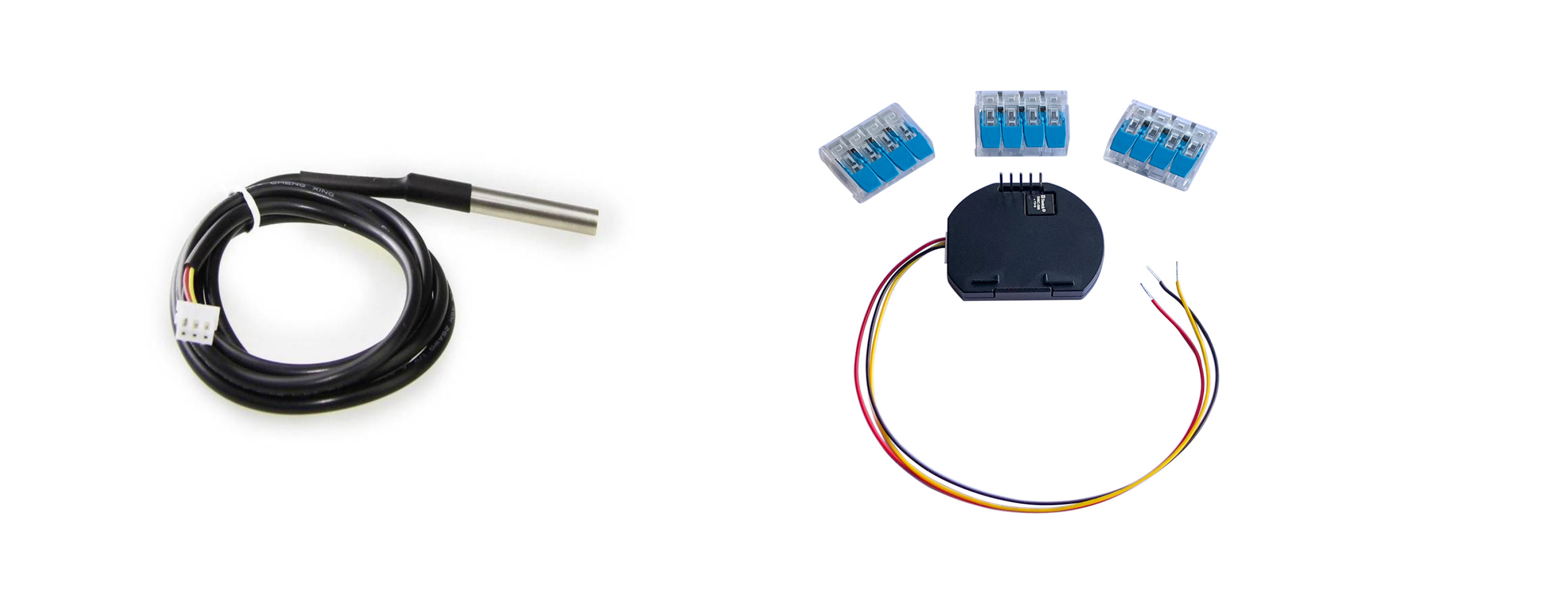
The tasmota driver can receive the temperature either via the related MQTT command or via a local temperature sensor (see example of a DS18B20 temperature sensor and a shelly temperature sensor addon below).
The default temperature input is MQTT. The following command can be used to select the local sensor as default input:
cmnd/Tasmota_Name/SENSORINPUTSET 1
Note
The default local temperature sensor is a DS18B20. In case a different Tasmota supported sensor is used, the following define in my_user_config.h is to be changed (or redefined in user_config_override.h) and a user specific tasmota software needs to be compiled:
#define THERMOSTAT_SENSOR_NAME "DS18B20" // Name of the local sensor to be used
MQTT temperature value and setpoint~
The following commands can be used to provide the driver with the temperature value of the room and the desired setpoint:
cmnd/Tasmota_Name/TEMPTARGETSET 22.5
cmnd/Tasmota_Name/TEMPMEASUREDSET 21.8
Examples for room temperature of 21.8°C and temperature setpoint of 22.5°C
There are several ways to send the MQTT room temperature. For the development and testing of this driver, a Raspberry Pi with Domoticz and a Z-Wave stick has been used to gather all room temperatures from Z-Wave sensors and send them to the respective Tasmota room thermostats.
Customization of the controller for best results~
The thermostat controller includes a default parameter set that targets a typical floor heating application for mid-sized rooms (< 20m2) with one heating circuit. The controller is however highly configurable via MQTT. The following sections will guide the user to adapt the main parameters to improve the performance of the thermostat controller via customization.
Enable the thermostat driver~
The thermostat driver is by default disabled. To enable it the following command can be used:
cmnd/Tasmota_Name/THERMOSTATMODESET 1
Set the controller in degrees Celsius or Fahrenheit~
The default temperature format is degrees Celsius. The format can be easily switched to degrees Fahrenheit via MQTT command, see below:
cmnd/Tasmota_Name/TEMPFORMATSET 1
Set the control strategy~
The control strategy by default is a Hybrid one. The hybrid control strategy mixes a so called "Ramp-Up" strategy (invention during the development of this driver, initially as a LUA script and ported to Tasmota later) and a PI one. The "Ramp-Up" strategy is typically used to reach as fast as possible the setpoint for big deltas between desired temperature and setpoint, the PI on the other hand for most part of the normal thermostat operation.
The control strategy can be however modified, if the Hybrid one is not desired, the PI or "Ramp-Up" mode, can be forced. For that purpose the following command can be used:
cmnd/Tasmota_Name/CONTROLLERMODESET 1
The value 1 forces the PI operation and the value 2 the "Ramp-Up" one.
PI controller main parameters~
Cycle time~
Depending on the heating system, the cycle time (PMW period) can be adapted. Very slow systems (high time constants) such as heating floor systems might need higher values (default value is 30 minutes), faster systems might need smaller cycle times. Below the command to adapt the cycle time can be found:
cmnd/Tasmota_Name/TIMEPICYCLESET 30
Proportional Band~
Depending on the dimensioning of your heating system, the proportional band of the controller might be increased (if it takes too long to reach setpoint) or reduced (very high overshoot). The default proportional gain is 4, which means that the duty cycle due to the proportional part of the PI controller will be 100% for temperature deltas between setpoint and room temperature equal or bigger than 4°C. Below the command to adapt the proportional band can be found:
cmnd/Tasmota_Name/PROPBANDSET 1
Note
With the command above, the PI controller will output a proportional time equivalent to 100% of the duty cycle for delta temperatures between setpoint and room temp. above 1°C (e.g., for big rooms with weak dimensioned heating circuit).
Reset Time~
The reset time is the time the PI controller takes to overcome steady-state errors. The default value for the reset time is 12000 seconds. This value can be for instance increased in case a stronger integral reaction of the controller is desired. Below the command to adapt the proportional band can be found:
cmnd/Tasmota_Name/TIMERESETSET 1800
Temperature for the anti-windup reset~
To avoid the accumulated error and therefore integral component of the PI controller to grow too much and produce a high overshoot, a temperature delta can be defined within the integrator will work. Outside this range the accumulated error and integral part will be set to 0. The default value for the integrator to work is 0.8°C. Below the command to adapt the anti-windup temperature can be found:
cmnd/Tasmota_Name/TEMPANTIWINDUPRESETSET 0.8
Temperature hysteresis~
A temperature hysteresis can be set to avoid any PI controller actions within a certain value around the setpoint. The default value for the hysteresis is 0.1°C. In well configured controller this value should be as low as possible to avoid unwanted temperature oscillations which reduce efficiency and therefore increase costs. Below the command to adapt the anti-windup temperature can be found:
cmnd/Tasmota_Name/TEMPHYSTSET 0.1
Maximum action of the controller~
The maximum On time (Duty Cycle) in minutes within a cycle can be set by this parameter. The default value is 20 minutes. This represents for the default cycle time of 30 minutes 2 thirds of the complete cycle. In case the controller takes too long to reach the setpoint, this value can be increased to values closer to the cycle time. Below the command to adapt the maximum action time can be found:
cmnd/Tasmota_Name/TIMEMAXACTIONSET 20
Minimum action of the controller~
The minimum On time (Duty Cycle) in minutes within a cycle can be set by this parameter. The default value is 4 minutes. Below the command to adapt the minimum action time can be found:
cmnd/Tasmota_Name/TIMEMINACTIONSET 4
It is very important to adapt this value to your heating system to obtain accurate temperature control
If the value is very low, in case of floor heating systems for instance, the heating actuators might not have enough time to open the valves and the temperature will drop (depending on the actuator open/close time could take from 1 to 3 minutes) if it is too high, there will be unwanted oscillations around the setpoint. One way to configure this value in heating mode is to manually tune it in worst case conditions (highest typically desired room temperature and lower winter temperature outside) checking that the proportional action generated by the controller is sufficient to raise slightly the temperature. If the temperature still goes down after the pulse plus delay time of the system and rises just once the accumulated error triggers integral actions then the value set is too low.
Ramp-Up controller main parameters~
Temperature delta to get into "Ramp-Up" mode~
When the controller is configured in Hybrid mode (default), the control strategy will be a mix between "Ramp-Up" (for big deltas between room temperature and setpoint) and PI (around the setpoint). The following parameter can be set to define the delta temperature (between measured and setpoint) above which the "Ramp-Up" controller will be active:
cmnd/Tasmota_Name/TEMPRUPDELTINSET 0.3
The default value is 0.4°C.
Time passed after latest setpoint change to get into "Ramp-Up" mode~
When the controller is configured in Hybrid mode (default), the activation of the "Ramp-Up" mode will not just depend on the defined temperature delta between measured and setpoint, but as well on the time in minutes passed since the last setpoint change occurred. This strategy matches the purpose of the "Ramp-Up" controller, which was developed to reach the desired temperature as fast as possible in very specific scenarios, e.g., after a night keeping the room temperature low. In hybrid mode, the controller active most part of the time should be the PI one. The following parameter can be used to define the time to allow switching to "Ramp-Up" in minutes.
cmnd/Tasmota_Name/TIMEALLOWRAMPUPSET 300
The default value is 300 minutes.
Cycle time~
Depending on the heating system, the cycle time (PMW period) can be adapted. Very slow systems (high time constants) such as heating floor systems might need higher values (default value is 30 minutes), faster systems might need smaller cycle times. The following parameter can be used to define the cycle time in minutes:
cmnd/Tasmota_Name/TIMERAMPUPCYCLESET 45
Maximum Ramp-Up time~
The maximum time the ramp-up phase of the controller shall be active can be configured (default value is 960 minutes). The following parameter can be used to define the ramp-up time in minutes:
cmnd/Tasmota_Name/TIMERAMPUPMAXSET 180
Thermostat persistent storage for configuration~
The thermostat driver stores all configured parameters over MQTT exclusively in RAM, it does not use flash due to the amount of the parameters. This means that at every restart the default parameters will be set again. To avoid this behavior rules can be set-up to reconfigure desired parameters at every restart. See below an example:
ON Power1#boot DO Backlog sensorinputset 1;controllermodeset 2;thermostatmodeset 1;temptargetset %mem1% ENDON
ON mqtt#connected DO Publish2 stat/TestTopic/targetTempValue {"Temp":%mem1%} ENDON
ON mem1#state DO Backlog temptargetset %value%;Publish2 stat/TestTopic/targetTempValue {"Temp":%mem1%} ENDON
Detecting an opened window by temperature drop~
When opening windows, temperature will drop significantly faster than is normal. During that period, heating is usually not desired. Following rules will detect a .3C drop in 1min and send the thermostat into a 15min timeout. Replace HTU21 with your sensor's name, if your Teleperiod is < 1min, consider using Tele-HTU21#Temperature.
ON Event#windowstop DO Backlog EnableOutputSet 0; Power 0; RuleTimer1 900 ENDON
ON Rules#Timer=1 DO EnableOutputSet 1 ENDON
ON HTU21#Temperature DO Var1 %value% ENDON
ON Time#Minute DO Backlog Var3 %Var2%; Sub3 .3; Var2 %Var1% ENDON
ON Var2#State<=%Var3% DO Event windowstop ENDON
Preventing stuck valves by forcing actuation~
When left in place for too long, radiator valves might seize. Following rules will force actuation every week in order to prevent this. A time of 600 seconds should be long enough for slow actuators to open fully, adjust yours as needed. If using above windowstop code, skip Rules#Timer=1 as you already have it set.
ON Event#forceactuate DO Backlog EnableOutputSet 0; Power 1; RuleTimer1 600 ENDON
ON Rules#Timer=1 DO EnableOutputSet 1 ENDON
ON Clock#Timer=1 DO Event forceactuate ENDON
Timers 1
Timer1 {"Enable":1,"Mode":0,"Time":"08:00","Window":0,"Days":"0100000","Repeat":1,"Output":1,"Action":3}
If you have a button on your controller, consider using it to trigger the forceactuate event. This allows you to request instant heating when feeling cold. Add to your rule:
ON Button1#State DO Event forceactuate ENDON
Advanced features~
Multi-controller~
The tasmota driver can be compiled to be used in devices with more than one output, allowing independent controllers for each one of the outputs. This feature has been successfully tested with a Sonoff 4CH PRO R2.
To increase the number of controller outputs, modify the value of the thermostat controller outputs in my_user_config.h or redefine it in user_config_override.h and compile a customized tasmota software.
#define THERMOSTAT_CONTROLLER_OUTPUTS 1 // Number of outputs to be controlled independently
Alternative outputs: PWM duty cycle~
The driver provides the possibility to read the duty cycle in % (0-100) of the actuated relay. Below the command to read the duty cycle can be found:
cmnd/Tasmota_Name/CTRDUTYCYCLEREAD
The physical switch of the output can as well be disabled via command. Below the command to disable it can be found:
cmnd/Tasmota_Name/ENABLEOUTPUTSET 0
Future improvements~
Cooling~
The controller offers the possibility to switch from heating to cooling. Due to lack of cooling setup at the time of the development of the driver, this feature has however not been properly tested. Testers for cooling are therefore welcomed.
The following MQTT command can be used to switch from heating (default) to cooling:
cmnd/Tasmota_Name/CLIMATEMODESET 1
Self learning process of the "Ramp-Up" controller to reduce overshoot~
The "Ramp-Up" controller evaluates the time constant of the system and predicts when to switch off the actuator to reach the desired temperature as fast as possible. This controller offers the best speed to reach the Setpoint. This controller will be improved by a learning process to evaluate how accurate the target value has been reached and therefore minimize gradually the overshoot. This feature will improve the behavior of the current controller which depending on the application and thermal capacity of the system might produce some overshoot. By default the controller set is the Hybrid one, enabling "Ramp-Up" for big temperature deltas between Setpoint and measured temperature and PI for smaller ones. If you are not satisfied with the performance of this controller in your system, you can disable it by MQTT and force the use of the PI controller exclusively (see Controller configuration section above).
PI Autotune~
A PI autotune feature following the Zigler-Nichols closed loop algorithm has been implemented. This feature is untested and will be further developed soon. To enable it for testing purposes add the following define in user_config_override.h and compile a customized tasmota software.
#define USE_PI_AUTOTUNING // (Ziegler-Nichols closed loop method)
Example~
The following chart shows the thermostat behavior in a forced air heated house:

The red shaded areas are where the thermostat commanded heat and the green line is the temperature. The temperature setpoint is 18 C at night and is then increased to 22.5 in the morning. This step demonstrates the ramp part of the hybrid control algorithm of the thermostat. Once the temperature is near the set point the thermostat switches to he PI algorithm. In the evenings the temperature is increased to 23.5 C.