There are several Tuya dimmer and switch variants made by various manufacturers. The switches range from 1 to 8 gangs. The dimmers are usually 1 gang. They dim mains voltage for various lighting types: incandescent, CFL, and LED. Consult the specific device for the type of bulbs and capacity it supports as well as the bulbs themselves to verify they support dimming.
Identification and Technical details~
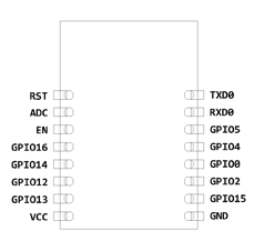
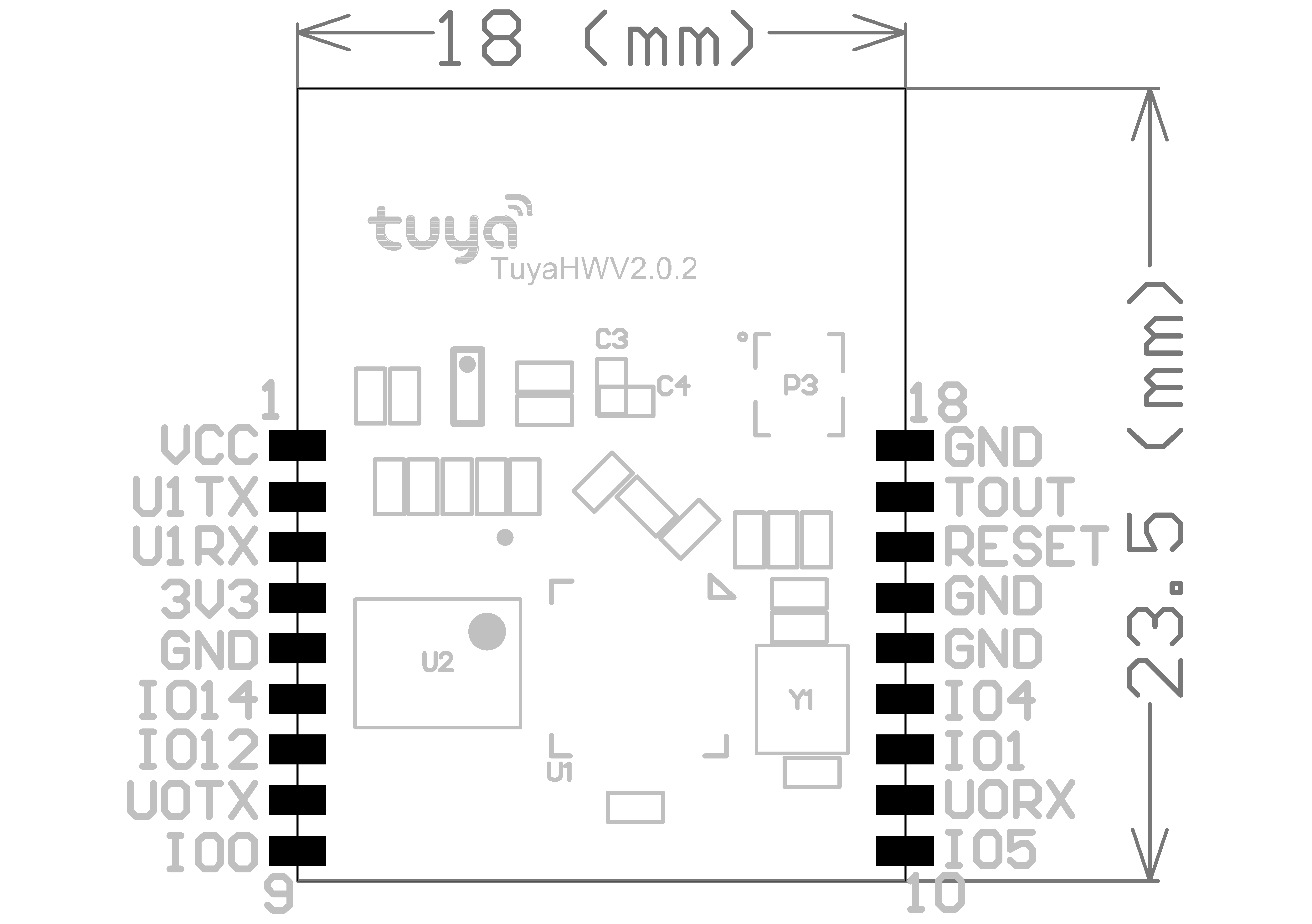
The basic identification of a Tuya device is when the device information references the "Tuya Smart", "SmartLife", or "Smart Living" app. These switches and dimmers are based on a Tuya TYWE3S Wi-Fi PCB module along with an MCU. TYWE3S is based on the ESP8266 which is supported by Tasmota.
The TYWE3S module mostly takes care of Wi-Fi and software features while the MCU controls the actual hardware (buttons, relays, dimmer, power measurement, etc). The MCU is interfaced to TYWE3S using the serial interface which connects to the Rx and Tx pins.
The easiest way to identify if your switch or dimmer uses MCU is by using a continuity tester (multimeter, ohmmeter) and checking continuity from the Rx and Tx pins on TYWE3S to any other chip. Then check the datasheet of that chip to see if it is an MCU.
Flashing - Preparation~
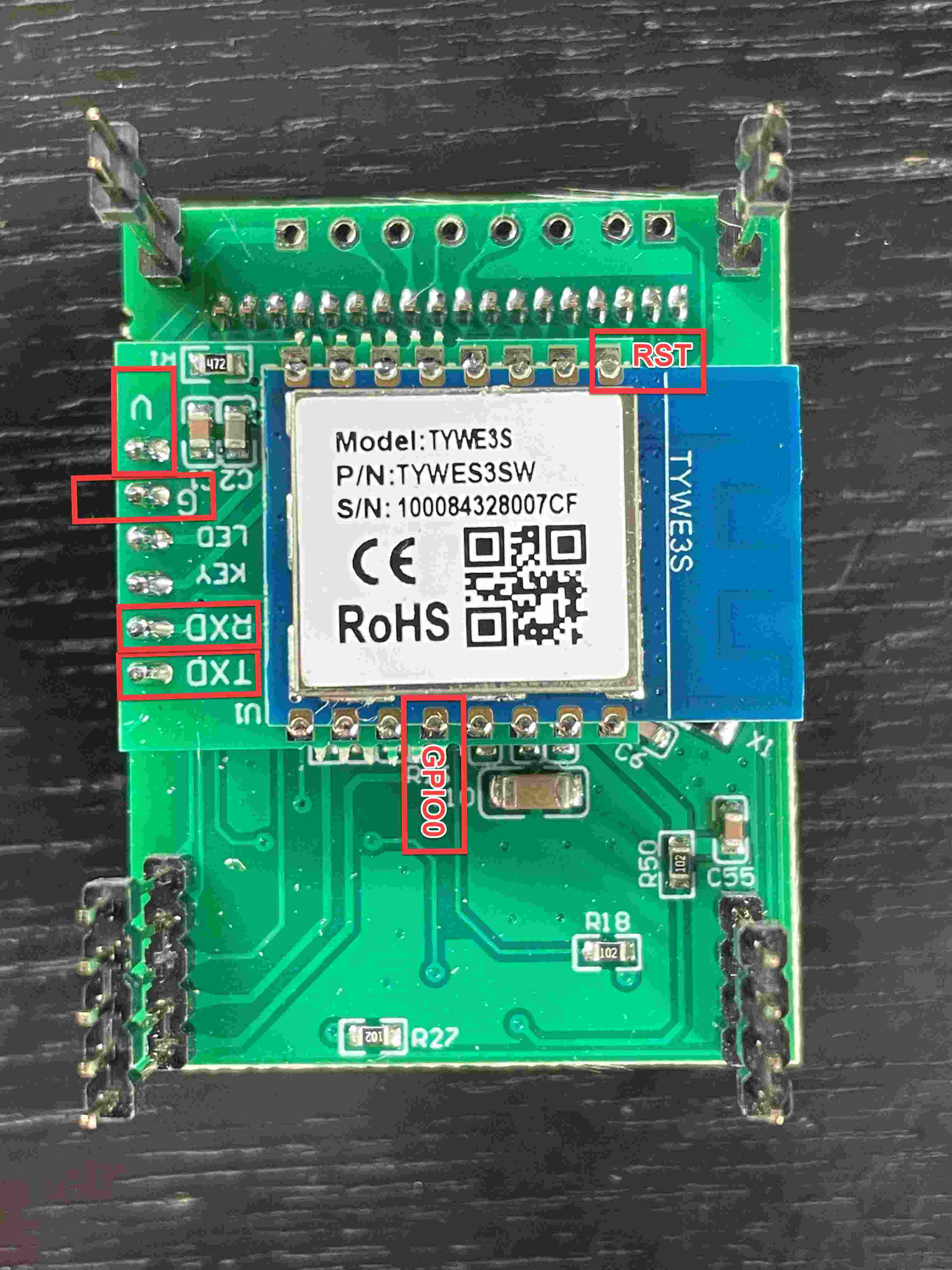
To boot the TYWE3S in flashing mode, GPIO0 needs to be connected to GND while powering up. It can be left grounded for the entire process. Flashing a TYWE3S connected to a MCU is a bit trickier than one without MCU. This is due the same Rx Tx pins used by MCU and serial programmer for flashing. The TYWE3S cannot be booted to flash mode with MCU sending data over the same pins. To be able to do that, we need to disable MCU from sending data over Rx and Tx pins. There are few ways to do it:
- Disconnect TYWE3S module from the rest of board. (Naah, too much work)
- Just break the Rx track from MCU to TYWE3S, flash and then reconnect. (Messy work, we want cleaner approach)
- Just keep MCU disabled while flashing TYWE3S without any soldering / cutting. (We like that)
The easiest is to keep MCU disabled is by identifying the NRST/RST (Reset) pin of the MCU from its datasheet and connect it to GND for the entire flashing process. This will keep MCU disabled while you flash TYWE3S. If there are some contacts or test points in switches that connect to the MCU, you might be lucky to find contacts for RST that you can easily solder onto. For some devices you need to disconnect RST after boot. An example for such a device is the Ketotek KTEM06.
TYWE3S Connection Options~
- 3D print a flashing Jig and use pogo pins to make nice and easy to use flashing jig
- Solder wires directly onto TYWE3S
- Use a jumper header like the one below and bend the pins to match VCC, Rx Tx GPIO0 and GND. You can just press the jumper header to the contacts during the flashing process

Flashing - Process~
Once you are done identifying the pins and ready to connect, BEFORE connecting USB to PC you need to connect them as follows:
NOTE : Use 3.3V NOT 5V
| TYWE3S | Serial Programmer |
|---|---|
| RX | TX |
| TX | RX |
| GPIO0 | GND |
| GND | GND |
| VCC | 3.3V |
If an MCU is present, bridge RST to GND on the MCU
Use a 6.6.0.10 Tasmota version or higher. There are lots of Tuya Serial fixes / features added in there and the tutorial below expects them.
Now you need to follow the commands explained in the flashing tutorial.
TIP: If you are using jumper headers use sleep 15 && before your commands, this would free your hand and give you some time to set the jumper pins and connect the USB to PC.
Configuration~
- Once Tasmota is flashed on the TYWE3S, just disconnect GND -> GPIO0 (and RST if there is an MCU), and power your device again from USB.
- On your PC, you should see a Wi-Fi network named
sonoff-xxxxwherexxxxis a number from the ESP's MAC address. - Connect to it and go to 192.168.4.1 in your browser. Enter the Wi-Fi credentials for your network and click save.
- Connect your PC back to your network. Now you need to find the IP of newly connected Tasmota device. Refer to this very good video from SuperHouseTV (ignore flashing information) about configuring Tasmota.
- Once you get to the Tasmota configuration you need to select
TuyaMCUmodule assign GPIO components as indicated below depending on your hardware. You already know the pin connections to the MCU.
| GPIO | Component |
|---|---|
| 01 | Tuya Rx (108) |
| 03 | Tuya Tx (107) |
| 13 | Tuya Rx (108) |
| 15 | Tuya Tx (107) |
- If the device is connecting fine to your network, now is the time to power it down and re-assemble it. Connect a test bulb (or to the final place if you don't mind testing there)
- Once this is saved and device is rebooted. Open the Tasmota configuration page and you should be able to use the Toggle button to toggle the dimmer or at least one of the gangs in a multi gang switch.
- Follow the process here depending on switch or dimmer.
Product Specific guides~
Otim Dimmer~
This Device is based on a Tuya Wi-Fi Module. Refer to "MCU Based Tuya Dimmers and Switches" for details.


Flashing and Setup Video Guide
These devices use a Tuya TYWE3S Wi-Fi PCB module. Once the switch is carefully popped open you will need to remove the ribbon cables for flashing and ease of soldering. An easy soldering method is to take several Dupont style jumper wires, cut one end off, and apply a bit of solder to each stripped end. This will keep the wire flexible and prevent any circuit board pads from ripping off. Apply a bit of solder to each pad necessary to flash (double check your pin-outs). Once the wire and pad have solder simply put the two together and apply a bit of heat and they will join together.
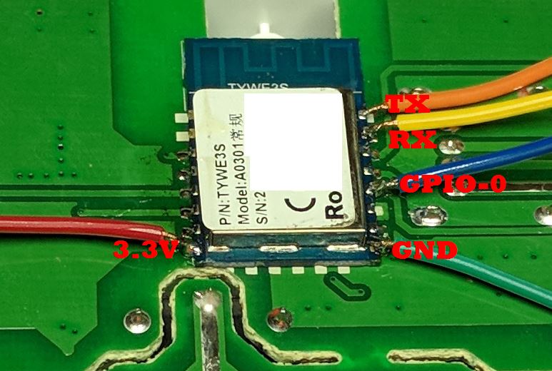
Attach the GPIO0 wire to ground during initial boot to flash. You may need to also connect MCU RST to GND during initial boot to get it into programming mode as described here. A 3-pin header bridged together works great with GPIO0, GND and the GND from the USB flasher attached. (TX pin to RX pin and RX pin to TX pin on USB flash adapter). Verify that you are using 3.3volts to flash, NOT 5V!
Product Links~
Costco Charging Essentials~
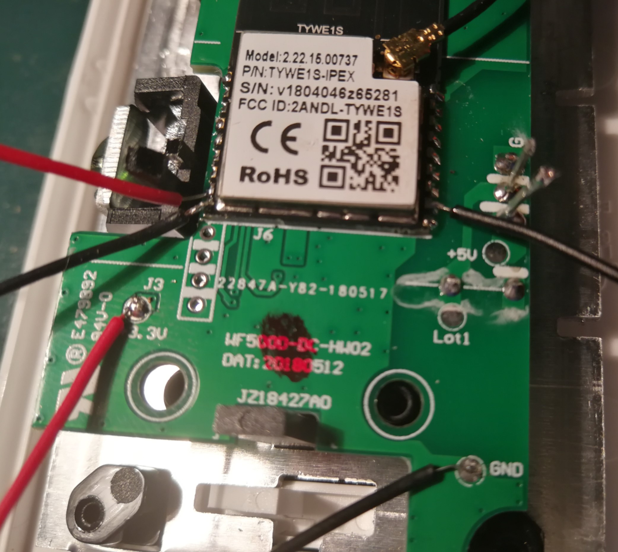
This devices use a Tuya TYWE1S Wi-Fi PCB module. And it uses U1TX (GPIO15) and U1RX (GPIO13) to communicate between ESP8266 and MCU, no other GPIO is used in this device.
Flashing~
The CE dimmer uses standard Tuya GPIO
Touch (EU and US) - Multiple manufacturers~
Flashing~
The procedure is similar to above, additionally NRST must be connected to GND during flashing.
Optional configuration (recommended)~
LedState 0 Only use the green LED for Wi-Fi/MQTT connectivity status.
Product Links~
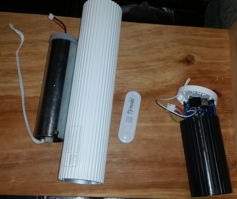
Zemismart Curtain Motor~
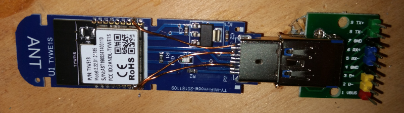
Curtain motors come in a confusing array. This one has a little Wi-Fi dongle, that looks like a USB stick. But it talks using 9600 8N1, not USB. This means we can unplug the Tuya Dongle and flash it without worrying about the PCI micro. Excellent.
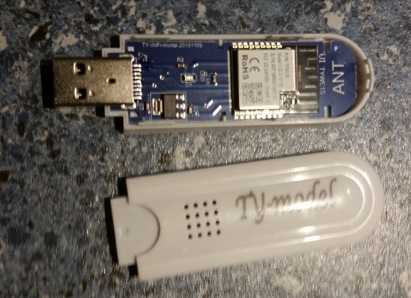
U1RX and U1TX, top right of the module are connected to the USB plug on D- and D+ respectively. This dongle uses a Tuya TYWE1S, which is an ESP8266 with 2MB flash. USB3 pin R- connects the onboard LED to the MCU via a 4k7 resistor. R+, T+, and T- are all unused and unconnected on the motor PCB, so I liberated them for soldering to GPIO0, U0RX and U0TX, to flash the chip.
- short GPIO0 and flash Tasmota
- Connect to your Wi-Fi and get MQTT and SSL working
- change to TuyaMCU with
module 54(will reboot) - Switch from U0RX/TX to U1RX/TX with
backlog gpio1 0; gpio3 0; gpio15 107; gpio13 108(will reboot) - Treat DpId 0x65 as a Dimmer with
tuyamcu 21,101 - Allow the dimmer to get down to 1% with
setoption69 0
And done. The curtain motor now presents as a Dimmer, with 100% full brightness = fully closed, and 0% full darkness = fully open.
The curtain motor also presents DpId 0x66 as a single event "Full Open" 00, "Full Close" 01, and "Stop" 02 command; but as of September 2019, I can't see how to get that working.
The curtain motor also presents DpId 0x67 as a Boolean. I have only seen value 0x01 in all my prodding. 55 aa 00 07 00 05 67 01 00 01 01 75 = 07 Status, 0005 length, 67 DpId, 01 type, 0001 length, 01 value, 75 checksum
Product Links~
DM_WF_MDV4 Leading edge dimmer~

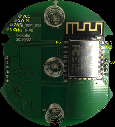
This is a 240V Leading Edge Dimmer with a TYWE3S controller and an STM8 MCU
Flashing~
The simplest approach is to use Tuya-Convert to flash the device
In order to flash via serial, the NRST pin of the STM8 needs to be grounded upon boot to disable it, this is brought out to a header pin, along with ground and VCC from the TYWE3S. Confirm by checking continuity with a multimeter
IO0 from the TYWE3s also needs to be grounded upon boot, otherwise it's normal tasmota flashing procedure.
Header J3 (STM8 debug interface) pins from left to right (Pin 1 is the square shaped) *VCC *STM8 SWIM (Pin 18) *Ground *STM8 NRST (Pin 4)


Config~
As per main TuyaMCU page using
| GPIO | Component |
|---|---|
| 01 | Tuya Rx (108) |
| 03 | Tuya Tx (107) |
Note that the push button is wired to the MCU (PA3 Pin 10) so it cannot be used by Tasmota. Similarly the devices has a bi-color LED where one color (green) is wired to the TYWE3S (GPIO14) and the other one (red) to the MCU (PC5 Pin15).
More information~
Bought from ebay
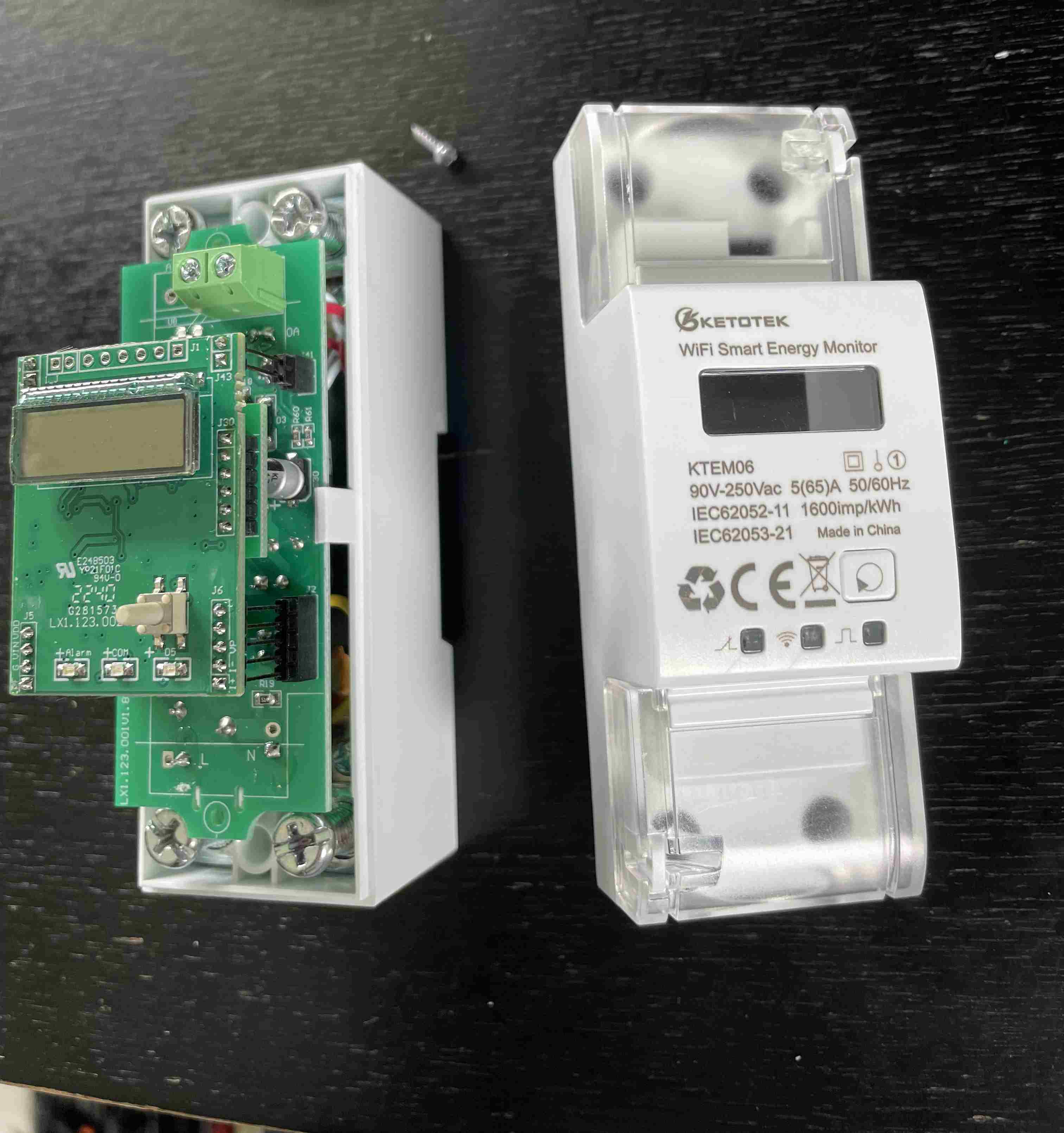
Ketotek KTEM06~
The KTEM06 is a single phase energy meter with a relay for switching for DIN rail mounting. This device is identical in construction with the TYWE3S-based version of HIKING DDS238-2.
Flashing~
Open the case to see the board with the display and the TYWE3S module on the backside. Remove the board and flip it around.
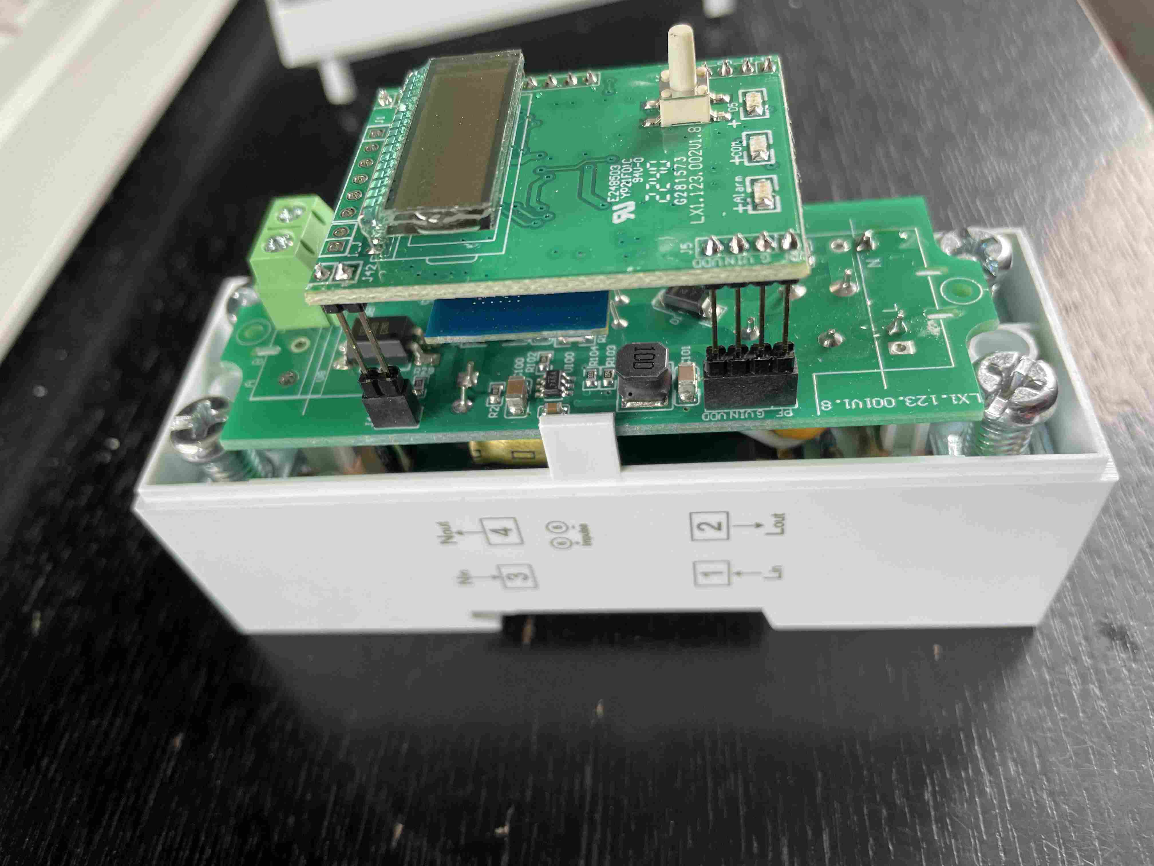
There is no need to unsolder the module from the MCU for flashing. You need to solder 6 wires to the module at the marked pins.
| PIN | Description |
|---|---|
| G | GND |
| V | 3.3V |
| TXD | to RXD of programmer |
| RXD | to TXD of programmer |
| GPIO0 | connect to GND while flashing |
| RST | connect to GND for booting, disconnect for flashing |
Flashing procedure
-
As usual, connect GND (G), RXD and TXD with the serial programmer. Connect GPIO0 to GND and keep it connected while flashing.
-
Connect RST to GND
-
Prepare Tasmotizer or your preferred tool for flashing.
-
Connect V to 3.3V
-
After 2-3 seconds disconnect RST
-
Start flashing
Configuration~
The ESP will not boot if you try to supply it with power from the serial programmer and having the display board unmounted. Unsolder the wires, mount the display board and close the case. Apply power to the connectors #1 and #3. Configure Wifi and complete the configuration with the information on Ketotek Single Phase Energy Monitor DIN Relay (KTEM06)
Remarks~
Different than described elsewhere it was not helpful to connect EN to 3.3V.
RST needed to be disconnected from GND to start flashing.
Some users report that flashing does not work because the serial programmer does not supply enough power. Using serial programmers based on CH340 seem to work. A workaround is to use an additional power supply.