Zigbee internals~
This page is for developers who want to understand how Zigbee2Tasmota (Z2T) works and its implementation details.
CC2530 Serial protocol~
The CC2530 is flashed with Texas Instrument ZNP Software version 1.2. The protocol is build on a serial communication between the main cpu and the CC2530.
Z-Stack 1.2 Monitor and Test API
Serial communication is configured as 8N1, 115200 bauds. We suggest to use GPIO13/15 because they have hardware serial support. Please note that there is only one usable hardware serial, either on GPIO1/3 or GPIO13/15.
To enable hardware serial on GPIO13/15 for Tasmota, set Serial 0 and restart. Otherwise Z2T will use Software serial provided by TasmotaSerial.
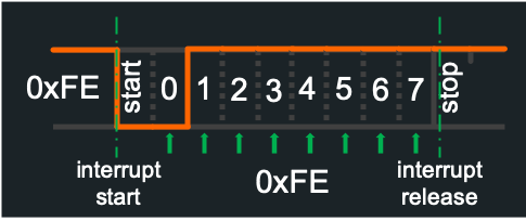
Receiving 115200 bauds in software is a timing challenge. Here is the anatomy of a byte transmitted in serial mode. Each bit is 8.7µs, or ~700 CPU cycles at 80MHz (1400 cycles at 160MHz).
It all starts with a LOW "start bit" that generates an interrupt transferred to TasmotaSerial. Then TasmotaSerial enters a tightly controlled loop to read each bit (least sifnificant first). The frame stops with a HIGH stop bit.

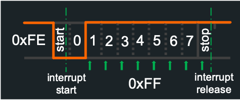
What can go wrong? Tasmota may be already handling an interrupt when the start bit arrives, potentially causing a shift by 1 bit and a wrong message.
Here is a 0xFE byte correctly received:
Same frame with a delay in the interrupt handler, and mistakenly read 0xFF:
TasmotaSerial has been improved to allow receiving a train of bytes withtout any disruption.
CC2530 generally sends all the bytes one after the other for a single ZNP message (up to 250 bytes). Instead of giving back control after the first byte, the TasmotaSerial interrupt handler continues to monitor the serial RX line for the next 4 bits and checks whether a new start bit arrived. It avoids any error after the first byte was received.
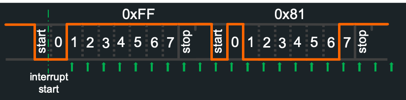
Still the first byte in the message could have been wrong. Fortunately, the first byte sent by ZNP is always 0xFE (see below). This means that if the interrupt arrives too late, Tasmota will read 0xFF instead of 0xFE. Z2T software does automatic error correction in this case, i.e. if the first byte received is 0xFF, it is automatically assumed to be 0xFE and the rest of the message is read normally.
With these two schemes, software serial for Zigbee proved to be extremely reliable, even at 80MHz. It is highly recommended though to run at 160MHz.
State machine - CC2530 initialization and configuration~
After Tasmota boots, it sends the sequence 410001 to force a CC2530 hardware reset. Z2T implements an asynchronous state machine to handle the initialization and configuration of the CC2530. The state machine sends commands and waits for responses (with time-outs) and takes different branches depending on the responses.
Instruction set~
The program is encoded as a list of 32 bits instructions, stored in Flash in the zb_prog array of type Zigbee_Instruction[]. There is a PC (program counter) that is increased at each tick (i.e. every 50ms).
The state machine has very simple instructions.
Instructions encoded with 4 bytes:
NOOP: no-operation, do nothing and move to the next instructionLABEL(x): no-operation, and defines a Label (8 bits) that can be called by code.GOTO(x): moves the PC to the instruction with LABEL(x)ZI_ON_ERROR_GOTO(x): if an error occurs, move to labelZI_ON_TIMEOUT_GOTO(x): if a timeout occurs, move to labelWAIT(y): wait formilliseconds (unsigned 16 bits). Note the granularity is 50ms and the wait is non-blocking WAIT_FOREVER: pause the state machine and wait for an external gotoSTOP: stop completely the state machine, only used after an unrecoverable error
Instructions encoded with 8 bytes:
CALL(f, x): call a function,is the address of the function of type uint32_t f(uint8_t). The input parameter is. The response is according to callbacks responses, except -1(time-out) simply continues the flow.LOG(m): log the string. can be in PROGMEM. For debugging only. MQTT_STATE(x, m): sends a MQTTZbStatemessage, with status codeand message . can be in PROGMEM. SEND(d): send a ZNP sequence to CC2530.is an array of , a macro computes automatically the size of the array. can be in PROGMEM. WAIT_RECV(x, m): wait for a specific messageto be received with a time-out of (uint16_t). Messages take into account are owly those matching the first 2 bytes. The complete message match is expected or an error is generated. If the message received is longer than , additional bytes are ignored WAIT_UNTIL(x, m): similar toWAIT_RECVbut message that don't match are ignored, until a matching message is received.ON_RECV_UNEXPECTED(f): if we received an unexpected (or unsupported) zigbee message, call function
Instructions encoded with 12 bytes:
WAIT_RECV_FUNC(x, m, f): similar toWAIT_RECVand a functionis called when the message matches.
All callbacks return int32_t with the following effect:
> 0: goto the corresponding label0: continue-1: signal a time-out< -1: trigger an error (goto on_error)
Initialization code for the state machine~
At Tasmota start-up, the state-machine fires. The current Z2T pseudo-code does the following:
Init:
- Set-up all the error handling functions
- Wait for 10.5 seconds after boot
- Send a RESET to CC2530
- Wait for CC2530 boot
Check configuration (if something is wrong, go to CONFIGURE):
- Check if the CC2530 was previously configured. It uses the same 1-byte Non-Volatile 0xF00 address and stores 0x55.
- Checks the Z-Stack version
- Checks the internal configuration: PanID, Ext PanID, Channel, PFGK and PFGKEN.
- If all good, emit an MQTT message saying Zigbee is configured
- Goto Start
Configure (only if needed):
- Emit an MQTT message for reconfiguration
- Do a factory reset of CC2530
- Reset the device once again
- Configure the following: PanId, Ext PanId, Channel, set type to Coordinator, PFKEY, PFKEYEN, Security Module
- Create NF 0xF00 location and store 0x55
- Goto Start
Start:
- Wait for CC2530 message saying the coordinator successfully started
- Query DeviceInfo
- Query Node Descriptor
- Query Active Endpoints
- Register 2 endpoints with profile 0x0104 (Home Automation) : 0x01 (default), 0x0B (for Xiaomi)
- Query Active Endpoints to verify 0x01 and 0x0B are active
- Close PermitJoin: don't accept any pairing
- Emit an MQTT message to indicate Zigbee started
- Mark Zigbee as initialized, accept incoming messages
- Load device configuration from Flash
- Query any lights declared with
ZbLightto read their current states - Pause the state machine
Pairing devices~
When you open pairing with ZbPermitJoin 1 (60 seconds) or ZbPermitJoin 99 (until next reboot), you allow new devices to join the network.
Example below is for an OSRAM Plug.
When a new devices joins, Z2T receives a TC Device Indication: ZDO_TC_DEV_IND (45CA) message with the device short (16 bits) address and IEEEAddress (64 bits).
16:39:26 MQT: tele/Zigbee_home/RESULT = {"ZbState":{"Status":30,"IEEEAddr":"0x7CB03EAA0A0292DD","ShortAddr":"0xF75D","PowerSource":true,"ReceiveWhenIdle":true,"Security":false}}
Z2T then queries the device for additional information, like ZbProbe would do.
First probe for Active Endpoint ZDO_ACTIVE_EP_REQ
16:39:26 MQT: tele/Zigbee_home/RESULT = {"ZbState":{"Status":32,"ActiveEndpoints":["0x03"]}}
Finally query for the following general attributes: Manufacturer Id and Model Id.
16:39:26 ZIG: ZbZCLRawReceived: {"0xF75D":{"0000/0004":"OSRAM","0000/0005":"Plug 01"}}
16:39:26 MQT: tele/tasmota/Zigbee_home/SENSOR = {"ZbReceived":{"0xF75D":{"Manufacturer":"OSRAM","ModelId":"Plug 01","Endpoint":3,"LinkQuality":36}}}
Code flow when a message is received~
Message Serial decoding~
Here is a detailed view of the code flow and transformations applied when a Zigbee message is received. It's simple but has many ramifications.
During the Tasmota event loop, Z2T first checks any incoming message by calling ZigbeeInputLoop(), and after parsing incoming messages, it sends any outgoing message by calling ZigbeeOutputLoop().
Note: outgoing messages are not sent directly but stacked into a buffer and sent once per event tick. This avoids lost messages when sending them too fast.
For ZNP, the serial buffer is read if there is any incoming data. The message is checked for checksum and put into a SBuffer object of maximum size of 256 bytes. If a message is ready, it calls ZigbeeProcessInput(znp_buffer)
For EZSP, the flow is a little more complex because multiple layers of decoding are required. The first layer receives the message and handles UART-EZSP protocol messages: ignores XON/XOFF, decodes ESCAPE characters, CANCEL... It then decodes according to the pseudo-random generator, and checks the final CRC. If ok, it calls the second stage via ZigbeeProcessInputRaw(ezsp_buffer).
Note: the green light of the ZBBridge Led_i 1 is set to blink when a message is received from EZSP (which does not mean an actual Zigbee radio message was received).
EZSP second stage decodes the ASH protocol, including ACK/NAK of messages, RSTACK (reset confirmation) and ERROR. In case of ERROR, the EZSP stack is not able to respond anymore and requires a complete reset. In this case a log entry is produced and the entire Tasmota is automatically restarted. This stage automatically sends ACK messages to confirm reception of messages. If a DATA frame is received, it then calls the third stage via ZigbeeProcessInputEZSP(buf).
The third stage of EZSP decoding extracts the message, logs if needed and then calls ZigbeeProcessInput(buf).
State machine handling~
The message is passed to the state machine that will either automatically match the message and pass to the next state, or pass it to the default handler.
When the stack is fully initialized, zigbee.init_phase == false, the default handler is ZNP_Recv_Default() for ZNP or EZ_Recv_Default() for EZSP.
For ZNP, ZDO messages are dispatched to the relevant handlers: ZDO_END_DEVICE_ANNCE_IND, ZDO_TC_DEV_IND, ZDO_PERMIT_JOIN_IND, ZDO_NODE_DESC_RSP, ZDO_ACTIVE_EP_RSP, ZDO_SIMPLE_DESC_RSP, ZDO_IEEE_ADDR_RSP, ZDO_BIND_RSP, ZDO_UNBIND_RSP, ZDO_MGMT_LQI_RSP, ZDO_MGMT_BIND_RSP. Note: PARENT_ANNCE is handled at ZNP level and not passed to the application.
AF_DATA_CONFIRM emits a log message, and data messages are handled in ZNP_ReceiveAfIncomingMessage(). The ZCL frame is decoded into a ZCLFrame object and sent to Z_IncomingMessage().
For EZSP, messages are directly dispatched for trustCenterJoinHandler, incomingRouteErrorHandler, permitJoining and messageSentHandler. All other incoming messages, including ZDO, are sent to EZ_IncomingMessage().
EZSP: EZ_IncomingMessage() then decodes ZDO messages and dispatches them: ZDO_Device_annce, ZDO_Active_EP_rsp, ZDO_IEEE_addr_rsp, ZDO_Simple_Desc_rsp, ZDO_Bind_rsp, Z_UnbindRsp, Z_MgmtLqiRsp, Z_MgmtBindRsp, ZDO_Parent_annce, ZDO_Parent_annce_rsp.
Other non-ZDO messages decoded into a ZCLFrame object and sent to Z_IncomingMessage().
Incoming messages handling: Z_IncomingMessage~
The starting point is Z_IncomingMessage() with a ZCLFrame object corresponding to the received Zigbee message.
Details of Z_IncomingMessage():
1. Log the raw message at LogLevel 3 (DEBUG)~
2. Update the LQI for the device~
3. Update the last_seen value~
4. Dispatch according to message type~
-
If
ZCL_DEFAULT_RESPONSE, log and ignore (it's just the device acknowledge for the last message). -
If
ZCL_REPORT_ATTRIBUTES, callparseReportAttributes(). This is the general case for sensor values (temperature...) -
If
ZCL_READ_ATTRIBUTES_RESPONSE, callparseReadAttributesResponse(). This happens as a response to reading attributes, and the handling is similar to the attribute reporting (although the syntax of the message is slightly different). -
If
ZCL_READ_ATTRIBUTES, callparseReadAttributes(). This happens rarely, typically when a device asks the coordinator for attributes like thelocal_time. -
If
ZCL_READ_REPORTING_CONFIGURATION_RESPONSE, callparseReadConfigAttributes(). This is the response toZbBindStatecommand. -
If
ZCL_CONFIGURE_REPORTING_RESPONSE, callparseConfigAttributes(). This is the response toZbBindcommand. -
For cluster specific commands, call
parseClusterSpecificCommand(). This is the general case when a command is received (for ex"Power":"toggle").
All the previous commands add attributes to a local attr_list object. These attributes are have a key of eiher Cluster/Attribute type of String type.
Note: it is important to keep attributes as Cluster/Attribute types so that we can later apply transformations on them.
Note2: LinkQuality, Device, Name, Group and Endpoint are special values that do are not registered as actual attributes.
Note3: BatteryPercentage is systematically added with the last known value to each attribute reporting.
6. Apply transformations to the attributes.~
There are many transformations that are required because some device use proprietary values, or we need to compute new values out of the existing attributes.
-
Reject Loopback If the message is sent from the coordinator to the coordinator itself, which can happen with broadcast message, it is discarded with DEBUG level log
loopback message, ignoring. -
Generate synthetic attributes
generateSyntheticAttributes(). This is mainly used for Xiaomi Aqara devices. Aqara uses cluster 0xFF01 and 0xFF02 to send structured messages. The good side is that it allows to send attributes from different clusters in a single message, whereas the ZCL standard would have required several messages. The bad side is that Aqara reuses the same attribute numbers for different value, and you need to know the device type to decode; which makes the whole process work only if the pairing process successfully got the ModelId. This is also used by Aqara Cube and Aqara vibration sensor to decode values. -
Remove invalid attributes
removeInvalidAttributes()Any value out of normal range is removed, for examplelumi.weatherreporting a temperature below -100.0°C is removed. -
Apply synonyms
applySynonymAttributes()Apply any synonym from the Zigbee plugin definitions on a per device basis. If matched, the synonym maps the attribute to a new cluster/attrid and applies a multiplier or divisor if required. -
Compute synthetic attributes
computeSyntheticAttributes(). This is used to add computed attributes or fix some bugs in devices. Currently it computes theBatteryPercentagefrom theBatteryVoltageif theBatteryPercentageis not already present. It computesSeaPressureusing the TasmotaAltitudesetting. It fixes an Eurotronic bug in the encoding ofPi Heating Demandwhich is sent in the 0..255 range instead of 0..100 range. It fixes the IKEA Remote battery value which is half what it needs to be. It captures multipliers and divisors for AC Voltage/Current/Power (cluster 0x0B04) and stores them in the Z_Data. -
Generate callbacks and timers
generateCallBacks(). This is used to register deferres callbacks. It is only used forOccypancyfor now. Many PIR sensors report"Occupancy":1but don't report the lack of occupancy. This function sets a timer to artificially generate"Occupancy":0after a definite amount of time (defaults to 90 seconds). -
Post-process attributes
Z_postProcessAttributes(). This function does the final transformation of attributes to their human readable format.
First the endpoint is added as suffix if SetOption101 1 is set, if the source endpoint is not 1, and if the device is known to have more than one endpoint (check with ZbStatus2).
Then the attribute is looked-up from the global Z_PostProcess table.
If the attribute is mapped into Z_Data, the value is saved into its corresponding object. See ZbData. This allows for keeping last seen values for the Web UI.
Similarly, some device specific values are recorded: ModelId, ManufacturerId, BatteryPercent.
If the attribute as a multiplier value, the raw value is multiplied/divided by this value (ex: Temperature raw value is 1/100th of degrees, so the raw value is divided by 100).
Finally the attribute name is replaced by its string value (ex: 0402/0000 is replace with Temperature).
7. Publish the final message to MQTT or defer the message.~
In the general case, attributes are not published immediately but kept in memory for a short period of time. This allows for debouncing of identical messages, and coalescing of values (Temperature, Pressure, Humidity) in a single MQTT message, even if there were received in 3 separate messages.
The default timer is a compile time #define USE_ZIGBEE_COALESCE_ATTR_TIMER with a default value of 350 ms.
Once a message is ready, it first checks if the value conflict with previously held values. If so, the previous message is immediately sent, and the new values are held in memory.
Then is sets a timer to publish the values after the timer expired.