BlitzWolf BW SHP4 UK Version
- Product Page: https://www.amazon.co.uk/gp/product/B07GJ26TCQ
Serial Connection~
Please see the Hardware Preparation page for general instructions.
MAKE SURE YOU DON'T HAVE IT PLUGGED IN WHEN DOING ANY OF THIS INCLUDING FLASHING - YOU HAVE BEEN WARNED.
AS ALWAYS, YOU DO ANY OF THIS AT YOUR OWN RISK.
Overview~
The UK version of the BW SHP works perfectly as module number 45 (BlitzWolf SHP) but is challenging to flash with Tasmota firmware for two reasons:
-
The case is glued; this is relatively easy to overcome as you can insert a very thin screwdriver into the case then simply slide it all the way around the perimeter to free off the glue.
-
A much bigger issue is that the programming pins for the esp8266 are underneath the PCB very close to the case, so there's no way to get to them easily. This is the biggest challenge to installing Tasmota.
There are three choices here:
-
Open the case, unsolder the main PCB from the live and neutral pins. This is very difficult to do without deforming the plastic protection on the pins themselves and needs a powerful soldering iron.
-
Open the case, bend the main PCB up from the case. I've done one this way and it's possible, but not ideal as the copper live and neutral bars could crack from fatigue.
In either of these two methods, you also have to glue the case back together before the plug is safe to use, otherwise if you try and pull it out of a socket the cover simply comes off, exposing all the mains potentials.
- Make a slot in the bottom of the case, exposing the programming pins. This is my recommended way of doing it because it doesn't risk damaging the case or having it come apart from improper gluing, nor does it potentially fatigue the power pins or deform their safety plastic. However it does leave a big hole in the bottom of the case!
That said, the hole is only accessible when the plug is not in a socket and you can always cover it with more plastic later.
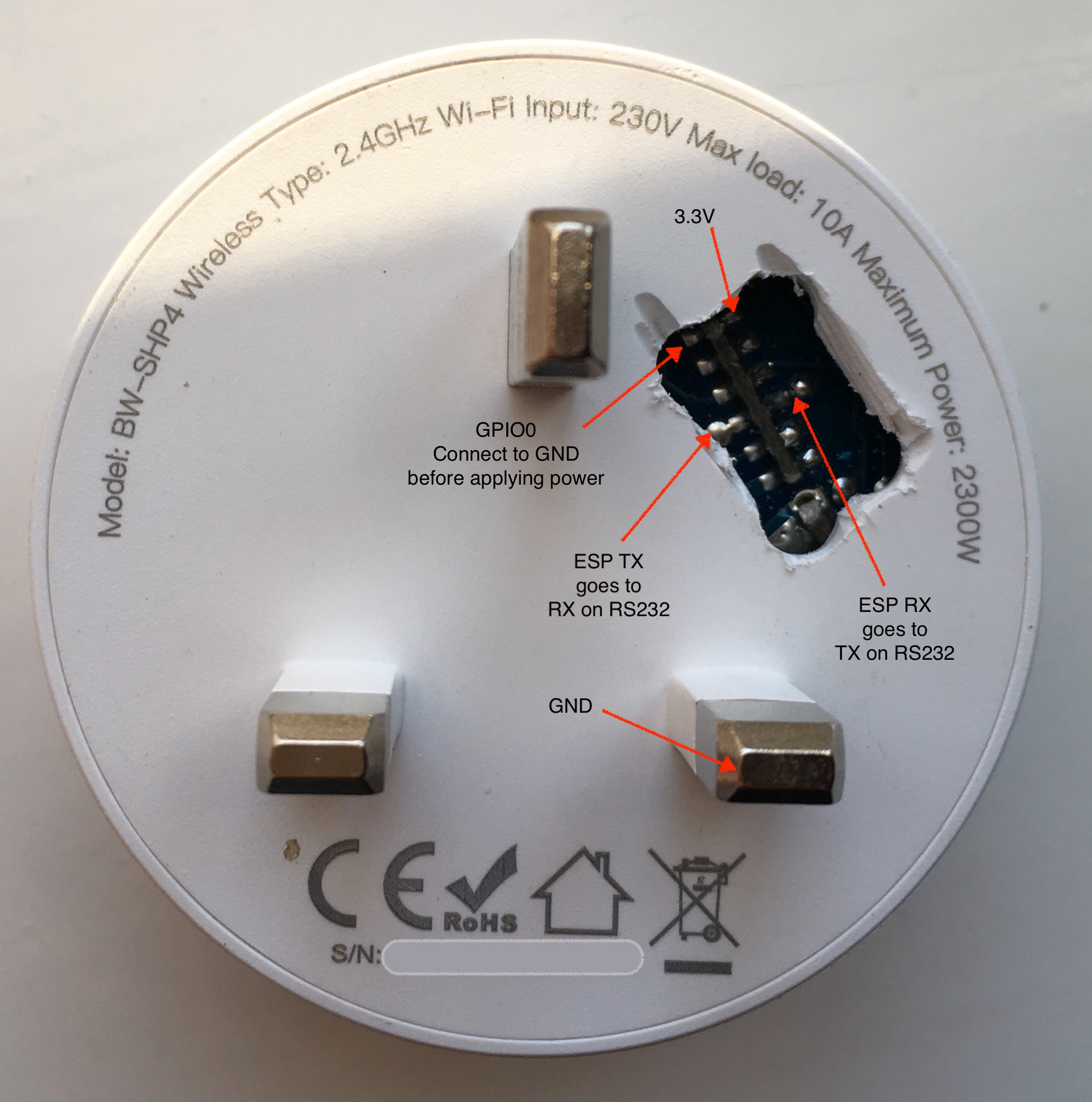
Holes in the base method~
If you want to go for method 3 ie hole in the base, this is where they should be. There's a better picture of this area of the PCB further down this page on a version I removed from its case.
Opening the case~
If you really feel a need to open the case - not recommended - get something very thin and fairly strong, push it into the base and pry a little until it goes in 3-4 millimetres. Then slowly rotate the plug with the wedge held in the opening so you end up pushing the top of the case away from the base all the way around.

Once you're done, this is what you'll find inside.

Gently pull the white shutter mechanism upwards and off the copper pins - it comes away very smoothly and easily but be careful to hold upright so the little spring doesn't pop out and disappear.
To get at the programming pins you then either have to desolder the live and neutral from the PCB and lift the whole thing off - strongly recommend you don't do this as you will almost certainly deform the plastic protecting the pins - or you will need to bend the PCB gently upwards so you can get at the underside. If you do that it will look like this.....

It's then pretty easy to flash using the pin connections I've annotated on the drawing - make sure you power it from low voltage though - DON'T EVER CONNECT TO THE MAINS TO FLASH OR WHEN CASE IS OPEN.
Once done, bend the PCB back into place, pop the white shutter assembly back on top and put the two case halves together with strong glue.
MAKE SURE THE GLUE IS WELL HELD AS OTHERWISE WHEN YOU PULL THE PLUG OUT OF A SOCKET THE TOP COULD COME OFF, EXPOSING ALL THE LIVE CONNECTIONS.
This is why I DON'T recommend opening the case to flash the firmware but instead suggest cutting a slot in the base and cover it afterwards.