CNSKOU CNSANKOU wall switches
General~
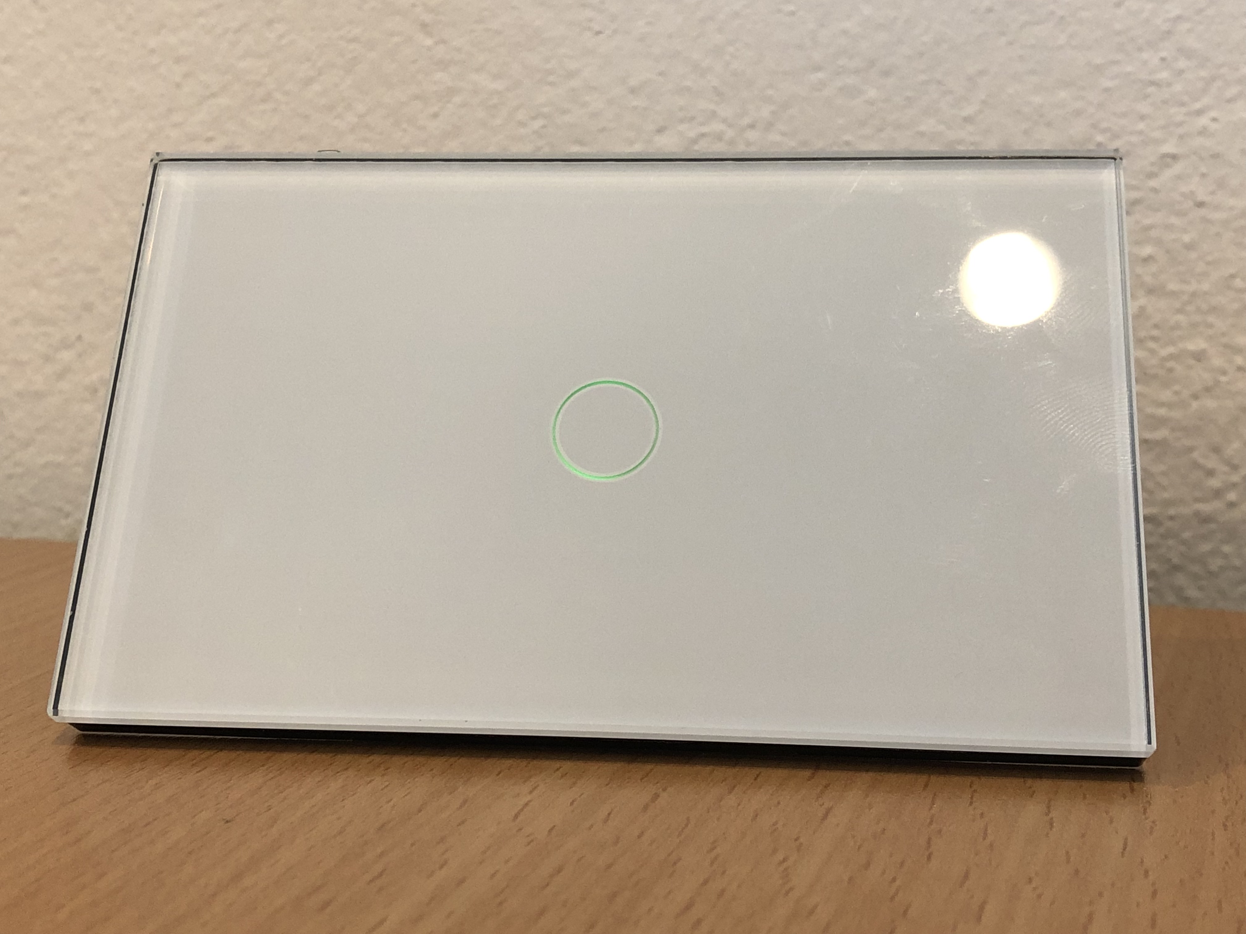
These CNSKOU / CNSANKOU wall switches (Chinese Sonoff clones) are sold on AliExpress and have a neutral design. They come in 1, 2 and 3 circuits and are easily mounted replacing your old wall switches. It measures 118mm wide by 72mm high, irrespective of the number of buttons, although it is also available in 86x86mm. The tempered glass front plate is available in white, black and gold colors. Despite it being advertised as a 'US' device, it will handle 90-250V AC input at 50/60Hz and is said to switch up to 10A per circuit. The same design is also available for use with a RF-remote, or as a traditional wall switch. There is a backlight indicator behind each button, which subtly shows green when the circuit is live and red when it is not. When physically pushing the button, there is an audio feedback. See here to view a video of the audio feedback.
The one interesting for Tasmota is of course the WiFi version, which connects to 2.4GHz networks, up to 802.11n. The switch comes pre-loaded with ITEAD software and works well with the EWeLink app.
Inside~
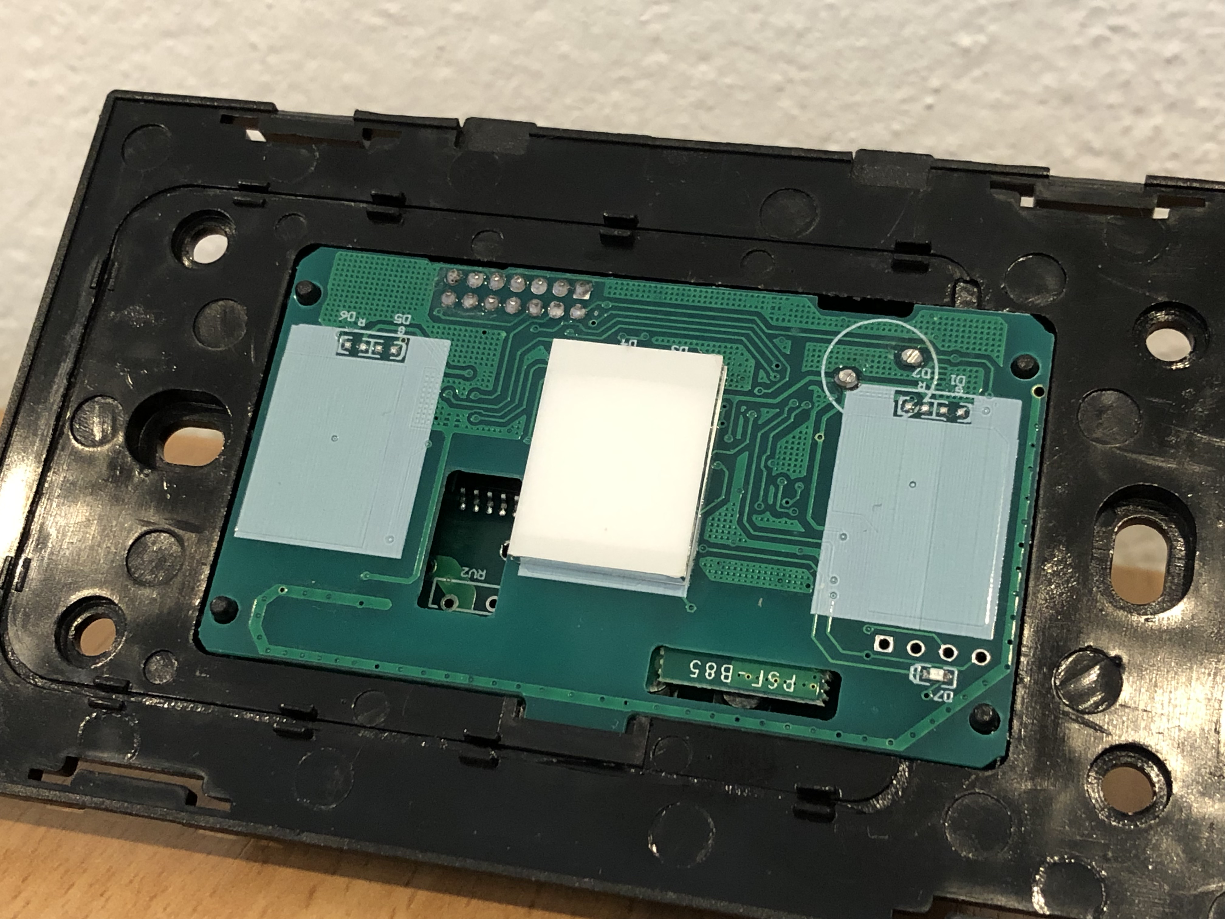
When opening the package, easily done by turning a screwdriver under the two plastic lips at the lower side of the switch, the first thing we see are the capacitive touch sensors mounted on the back of the low-voltage board.
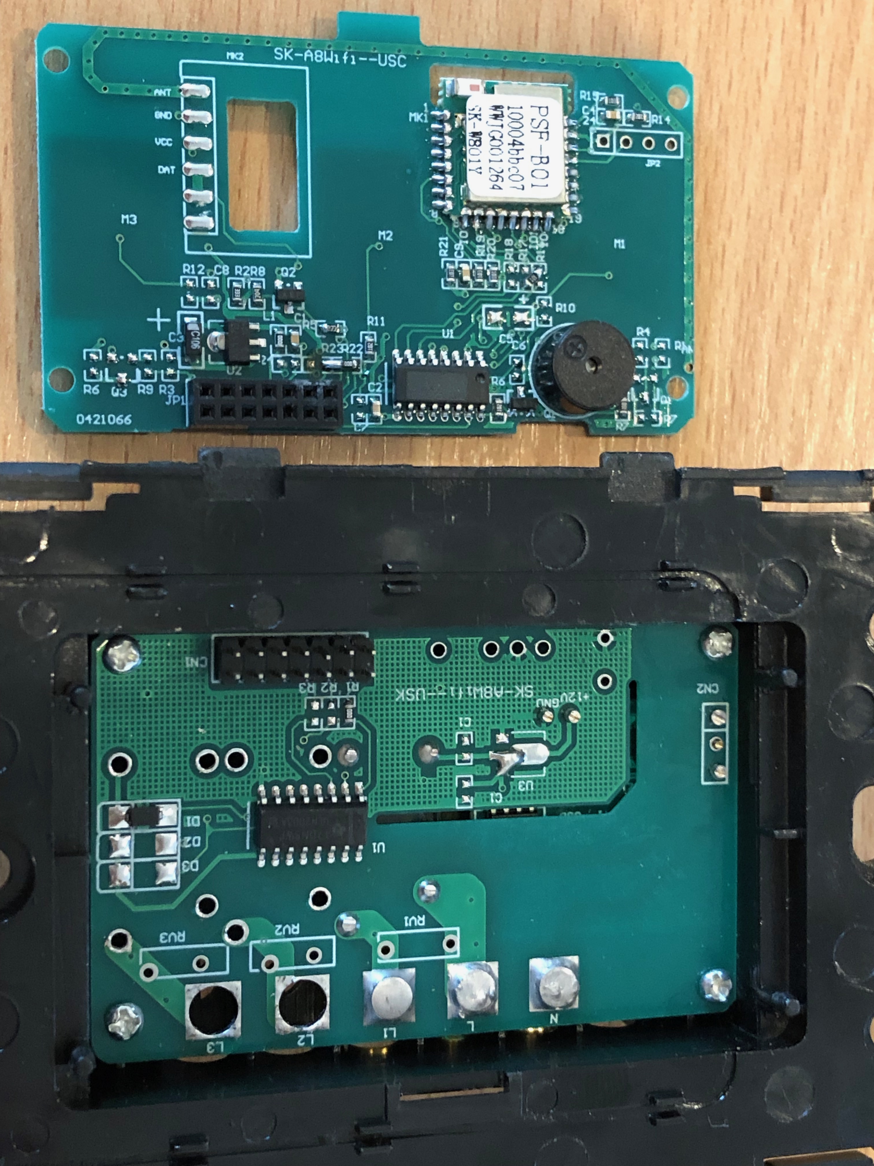
The low-voltage board is connected through a 14-pin connector to the mains board, and contains an ESP8285, piezo buzzer (should you wish to remove that audio feedback!) and a number of additional components. The ESP8285 is of course compatible with the ESP8266 albeit with only 1MB flash storage.
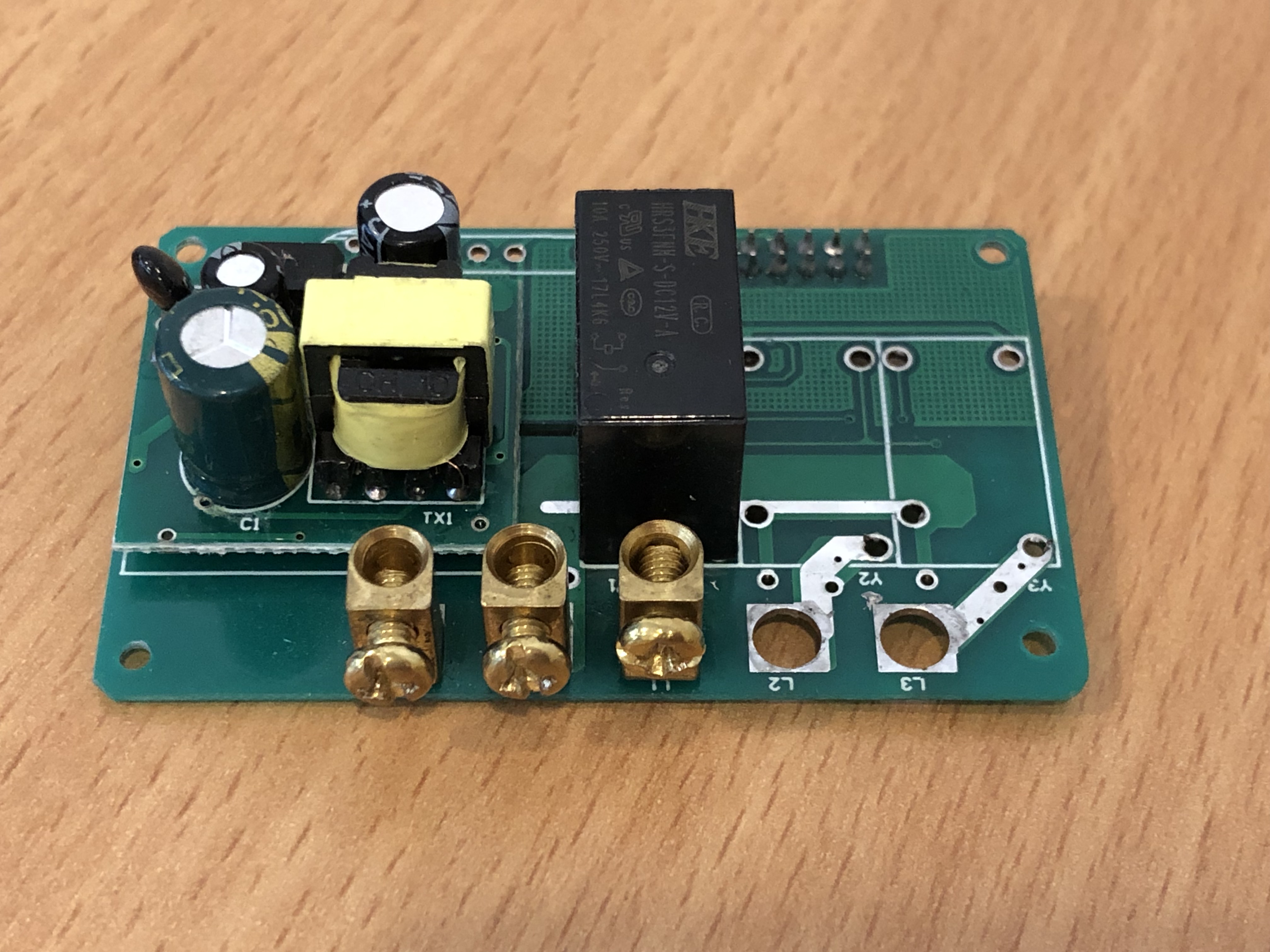
The mains-voltage board contains the mains connection points, a TI ULN2003A relay driver and 1-3 relays and a tiny little board containing a power supply for the low-voltage bits.
Flashing~
The most interesting part is of course how we flash this device with Tasmota. To do this, do not connect the device to mains power and carefully remove the low-voltage board as this is all you'll need.
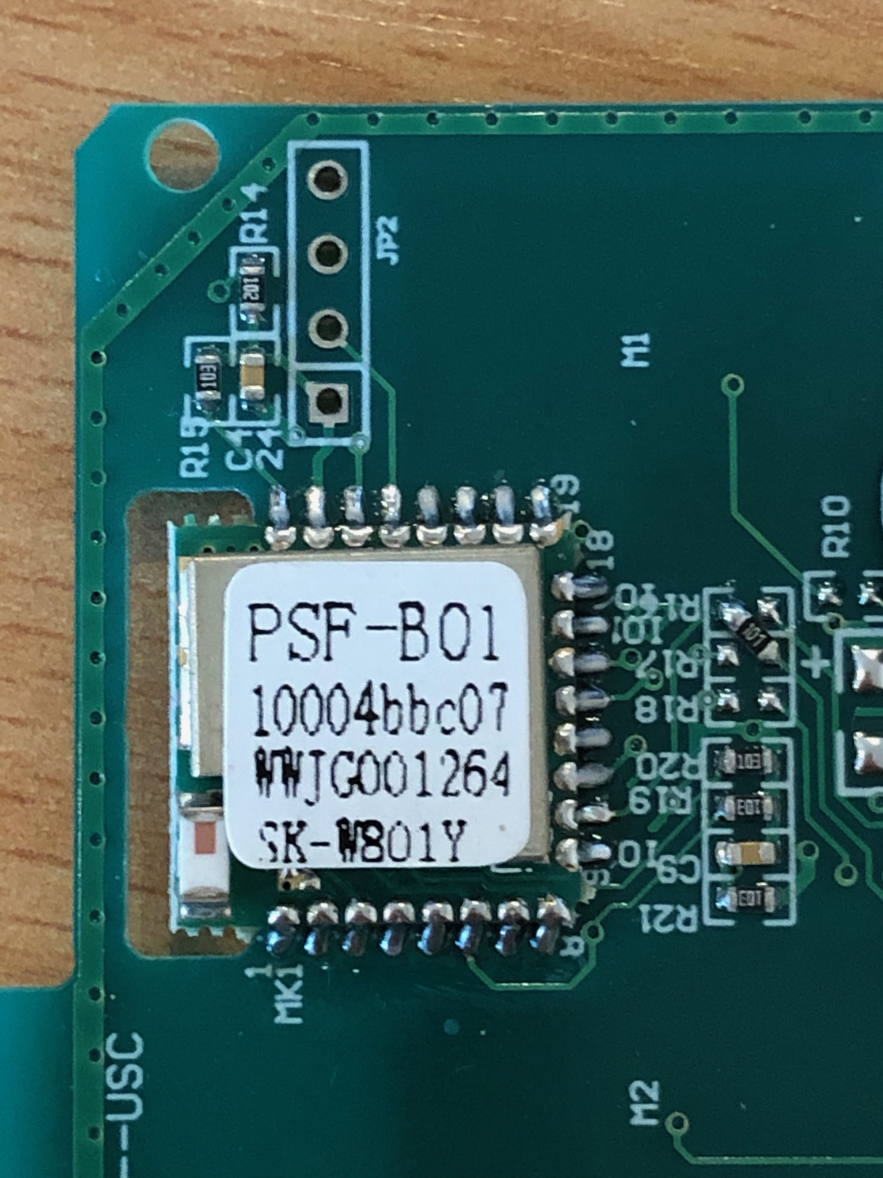
Notice the 4 connection points just above the ESP8285, which is where you'll connect (from square pad up) 3v3, RX, TX and GND. I found that normal DuPont jumper wires provide a secure enough connection, but you may wish to solder on a few header pins.
In order to get the ESP8285 into programming mode, you'll also need to connect GPIO0 to GND. There is no easily accessible connection point for GPIO0 and no buttons are provided on the board. I found the easiest way is to just use a normal jumper cable and manually hold it up against pin 10 (GPIO0) for a few seconds while the power is connected to the chip. Pin 10 is the second pin of the 'pin 9-16' row, on the right hand side of the chip in the image above.
Use the usual method for flashing, undoubtedly documented better elsewhere than I ever could.
Once Tasmota was up and running, I used the Sonoff T1 US module type.