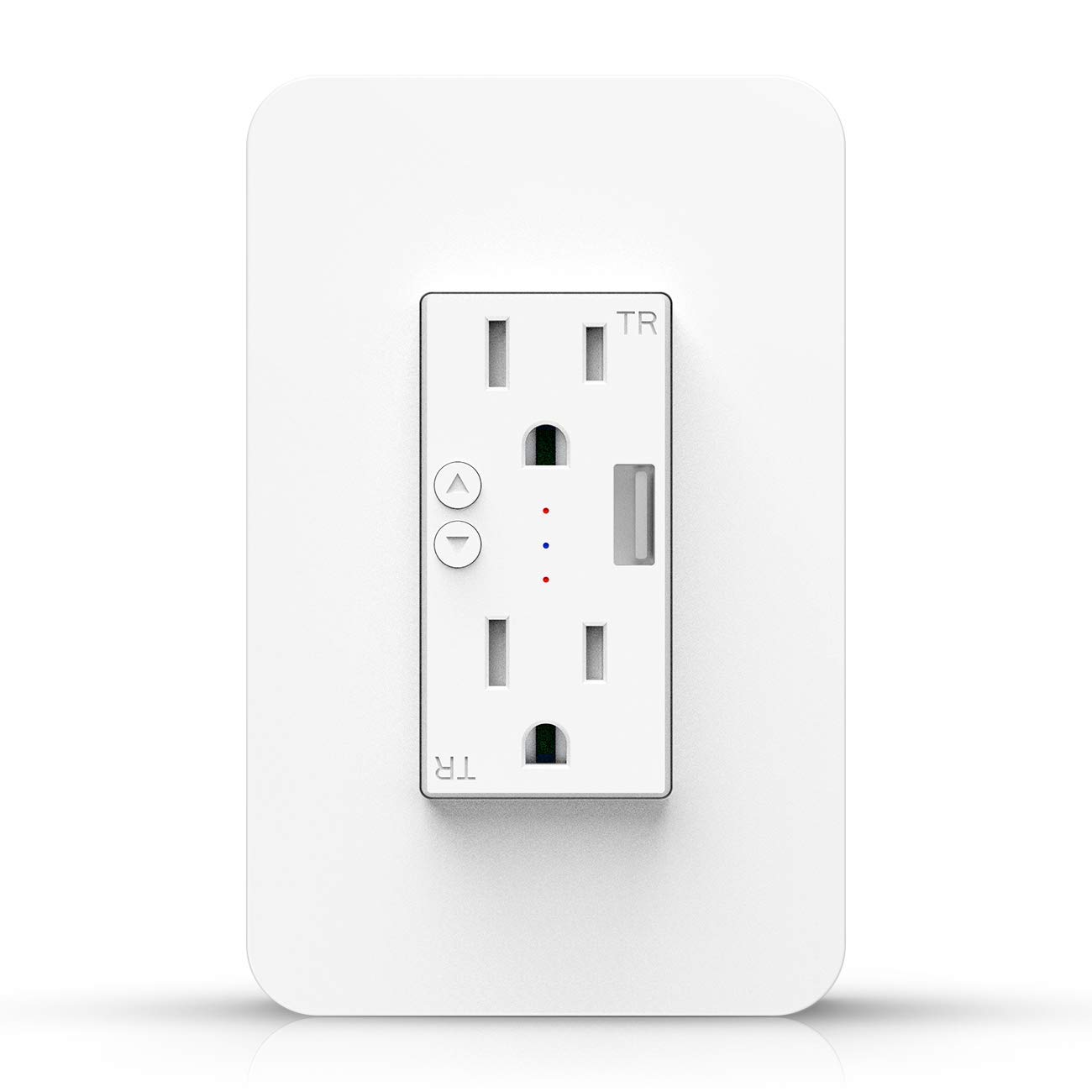
Kesen KS 604S
This Tuya Wi-Fi module ESP8266 based device has a really attractive form factor and functionality (in-wall, single gang, dual outlet, USB port, each individually controllable).
This device can be most easily flashed using using Tuya-Convert. Others have reported that flashing this device by attaching leads to the serial interface requires disassembling and unsoldering the internal AC components to get access to the needed contacts, however an AliBaba device was successfully flashed by connecting to the four terminals at the bottom of the back circuit board (3v3, Tx, Rx, G) and connecting pin D3 in block J7 to ground while booting and during the flashing process.
Shopping~
Configuration~
It appears that there are different versions of the KS-604S. The device that @DavinKD flashed (likely purchased from Amazon in early to mid March 2019) has a different GPIO configuration than devices purchased from Alibaba in late March.
Rear

Amazon Device~
{"NAME":"KS-604S","GPIO":[255,255,56,255,255,17,255,255,22,21,255,255,18],"FLAG":1,"BASE":18}
| GPIO | Function | Configuration |
|---|---|---|
| 2 | Device Status (Green) | LED1i (56) |
| 5 | Top Button | Button1 (17) |
| 12 | Bottom Receptacle | Relay2 (22) |
| 13 | Top Receptacle | Relay1 (21) |
| 16 | Bottom Button | Button2 (18) |
The USB port on this variant is not switchable.
Alibaba Device~
{"NAME":"KS-604S","GPIO":[158,255,255,17,56,18,255,255,22,21,57,23,255],"FLAG":0,"BASE":18}
| GPIO | Function | Configuration |
|---|---|---|
| 0 | Device Status (Green) | LEDLinki (158) |
| 3 | Top Button | Button1 (17) |
| 4 | Top LED (Orange) | LED1i (56) |
| 5 | Bottom Button | Button2 (18) |
| 12 | Bottom Receptacle | Relay2 (22) |
| 13 | Top Receptacle | Relay1 (21) |
| 14 | Bottom LED (Orange) | LED2i (57) |
| 15 | USB Port | Relay3 (23) |
This configuration requires the LedLinki Component (introduced in 6.5.0.12) to associate the GPIO to the status LED indicator. In order for the LED power indicators to follow the state of each receptacle relay, LedState must be set to show the power state on the LEDs. Select the desired power on state for the device's relays using PowerOnState and/or a System#Boot triggered rule. This device also requires SetOption63 (introduced in 6.5.0.9) in order to disable relay power feedback state scanning at restart.
The following Console statements define the necessary settings and rules as described above.
Backlog SerialLog 0; PowerOnState 0; SetOption63 1; LEDState 1
Rule1 ON System#Boot DO Power3 On ENDON    # Turn the USB port on
Rule1 1