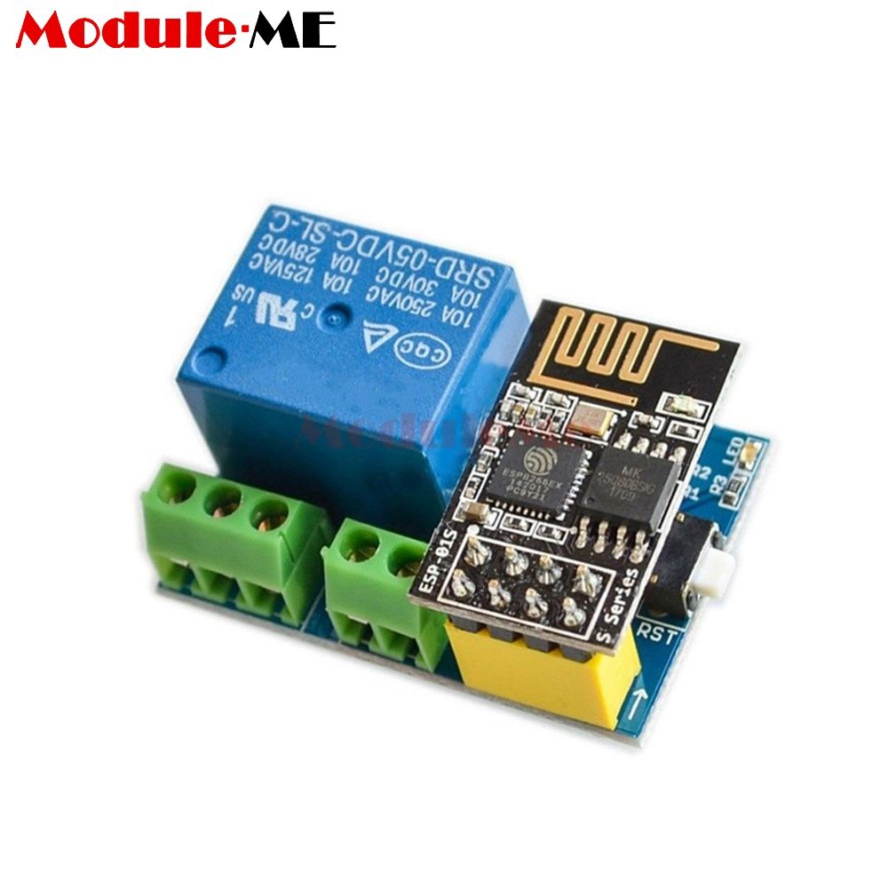
LC Technology WiFi Relay
LC Technology WiFi Relay - Single Relay~
The LC Technology relay devices use GPIO1 and GPIO3 for the serial communications used to control the relays. You do not need to specify these in the template. SerialSend uses these standard serial communications GPIO by default.
In order to use LC Technology WiFi Relay for 1 relay version:
- Set module to Generic (18) (in module configuration and click save)
- Set D3 GPIO0 as Relay1 (21) (in module configuration and click save)
- Disable SerialLog (type
seriallog 0in the Tasmota console) - Add the following rules typing in the console:
Rule1 on System#Boot do Backlog Baudrate 9600; SerialSend5 0 endon on Power1#State=1 do SerialSend5 A00101A2 endon on Power1#State=0 do SerialSend5 A00100A1 endon - Enable the rule (type
rule1 1in the Tasmota console) - Note: If you use LC Technology v1.2 and this rule does not work, try to use 115200 baudrate
- Note: If that doesn't work for you, you may find that using
Power1#Bootas the event to trigger the baud rate setting (instead ofSystem#Boot) works, as it did for me. So the alternate rule is:on Power1#Boot do Backlog Baudrate 9600; SerialSend5 0 endon on Power1#State=1 do SerialSend5 A00101A2 endon on Power1#State=0 do SerialSend5 A00100A1 endon
LC Technology WiFi Relay - Dual Relay (note, older versions of this board used a baud rate of 9600, so if 115200 doesn't work, try 9600)~
To configure an LC Technology ESP8266 Relay X2, use the following settings...
- Set module to Generic (in module configuration and click save)
- Set GPIO0 and GPIO2 as Relay1 and Relay 2 (in module configuration and click save)
- Disable SerialLog (type
seriallog 0in the Tasmota console) - Add the following rules typing in the Tasmota console:
Rule1 on System#Boot do Backlog Baudrate 9600; SerialSend5 0 endon on Power1#State=1 do SerialSend5 A00101A2 endon on Power1#State=0 do SerialSend5 A00100A1 endon on Power2#State=1 do SerialSend5 A00201A3 endon on Power2#State=0 do SerialSend5 A00200A2 endon - Enable the rule (type
rule1 1in the Tasmota console)
LC Technology WiFi Relay - Quad Relay~
Info
The template provided below did not work on an ESP-01 running Tasmota 8.1.0 nor on an ESP-01S running Tasmota 14.2.0. If after setting the template string you do not see the options to configure the relevant GPIO pins, in configuration open Configure Template and manually configure GPIO0, GPIO2, GPIO4 and GPIO5 as Relay1, Relay2, Relay3 and Relay4.
- In configuration open
Configure Otherpaste this template and select activate{"NAME":"LC Technology 4CH Relay","GPIO":[52,255,17,255,255,255,255,255,21,22,23,24,255],"FLAG":0,"BASE":18} - Open
Configure Moduleand set GPIO0, GPIO2, GPIO4 and GPIO5 as Relay1, Relay2, Relay3 and Relay4. Click Save. - Disable SerialLog (type
seriallog 0in the Tasmota console)
Enter this command in console (configure the 1st rule)
Rule1
 on System#Boot do Backlog Baudrate 115200; SerialSend5 0 endon
 on Power1#State=1 do SerialSend5 A00101A2 endon
 on Power1#State=0 do SerialSend5 A00100A1 endon
 on Power2#State=1 do SerialSend5 A00201A3 endon
 on Power2#State=0 do SerialSend5 A00200A2 endon
 on Power3#State=1 do SerialSend5 A00301A4 endon
 on Power3#State=0 do SerialSend5 A00300A3 endon
 on Power4#State=1 do SerialSend5 A00401A5 endon
 on Power4#State=0 do SerialSend5 A00400A4 endon
Info
Make sure the jumper connectors on the three pairs of pins on the board are connected correctly. In my case, the ESP-01's TX and RX pins are connected to the middle pair of pins while the other microcontroller's RX and TX pins are connected to the pair of pins farthest from the ESP-01 (and closest to the microcontroller). These need to be connected via jumpers for the two to communicate.
Info
Older versions of this board used a baud rate of 9600, so if 115200 doesn't work, try 9600. To do so, replace the first line of Rule1 with on System#Boot do Backlog Baudrate 9600; SerialSend5 0 endon.
Enable the rule (type rule1 1 in the Tasmota console). What this rule does is it sends serial commands to the second microcontroller on the board telling it to switch the respective relays on or off. The ESP-01 does not switch the relays itself.
At this point, head back to the main menu and try toggling the different relays. If the relays work, you've successfully set up your relay board. If not, continue below.
Switching to Mode 1~
First, check the LEDs on the board. If LED D5 is on (blue on my board, the middle LED) then the controller is in Mode 2. By pressing the correct button during power up you can change back to Mode 1. Which button you need to press seems to vary between versions of this board. Try holding S1 during power up. If LED D7 turns on (red in my case) and LED D5 is off you've switched to Mode 1. If not, remove power and repeat with button S2. Be careful as when you press the wrong button afterwards you again change modes again! Again, go to the main menu and try toggling the relays. Should they still not work continue below.
Configuring the Nuvoton N76E003AT20~
Newer versions of the board use the Nuvoton N76E003AT20 as its host microcontroller similary to the LC Technology WiFi Relay X2. This microcontroller requires a special configuration for it to start listening to serial commands. We need to add a new rule that sends this configuration to the N76E003AT20. However, if we combine this with our rule for turning on and off the relays, the rule gets too big and won't be accepted. We thus split it up into two rules.
Rule 1
 on System#Boot do Backlog Baudrate 115200 endon
 on SerialReceived#Data=41542B5253540D0A do SerialSend5 5749464920434f4e4e45435445440a5749464920474f542049500a41542b4349504d55583d310a41542b4349505345525645523d312c383038300a41542b43495053544f3d333630 endon
Rule2
 on Power1#State=1 do SerialSend5 A00101A2 endon
 on Power1#State=0 do SerialSend5 A00100A1 endon
 on Power2#State=1 do SerialSend5 A00201A3 endon
 on Power2#State=0 do SerialSend5 A00200A2 endon
 on Power3#State=1 do SerialSend5 A00301A4 endon
 on Power3#State=0 do SerialSend5 A00300A3 endon
 on Power4#State=1 do SerialSend5 A00401A5 endon
 on Power4#State=0 do SerialSend5 A00400A4 endon
rule1 1 and rule2 1. Head back to the main menu and try toggling the relays. They should now switch as expected. Info
For more information on what Rule1 does, see the explanation in the section on the X2.
LC Technology WiFi Relay X2 with Nuvoton N76E003AT20~
Note: This version of the board has the Nuvoton N76E003AT20 as its host microcontroller instead of STC15F104W. This device requires a special configuration for it to start listening to serial commands.
Use the following device template, configurable in Configure Other:
{"NAME":"LC-ESP01-2R-5V","GPIO":[0,148,0,149,0,0,0,0,21,22,0,0,0],"FLAG":0,"BASE":18}
Add the following rules:
on System#Boot do Backlog Baudrate 115200 endon
on SerialReceived#Data=41542B5253540D0A do SerialSend5 5749464920434f4e4e45435445440a5749464920474f542049500a41542b4349504d55583d310a41542b4349505345525645523d312c383038300a41542b43495053544f3d333630 endon
on Power1#State=1 do SerialSend5 A00101A2 endon
on Power1#State=0 do SerialSend5 A00100A1 endon
on Power2#State=1 do SerialSend5 A00201A3 endon
on Power2#State=0 do SerialSend5 A00200A2 endon
Here's what the above code does line per line:
- Sets the serial baud rate to 115200 (this seems to be the default for the Nuvoton LCTech Relay)
- This sends a certain stream of serial messages (in hex) below after receiving AT+RST (41542B5253540D0A in hex) from the NUVOTON devices. This message seems to make the NUVOTON enter listening mode. The long stream of hex messages for sending is equivalent to the ff. key in ASCII:
WIFI CONNECTED WIFI GOT IP AT+CIPMUX=1 AT+CIPSERVER=1,8080 AT+CIPSTO=360 * Open * The PowerX#State=xxx... messages are triggers to send serial messages to the NUVOTON chip.
Do not forget to enable the rule.
After the device receives the bypass key, it wouldn't immediately respond to commands. The ESP has to wait for the following return messages echoed back to Serial first:
After these messages are sent back by Nuvoton to the ESP, the green LED beside the green LED will start blinking once a second. From here you can verify that the relay indeed starts to receive commands from the ESP.
## LC Technology WiFi Relay X4 with Nuvoton N76E003AT20
Note: This version of the board has the Nuvoton N76E003AT20 as its host microcontroller instead of STC15F104W. Becareful, not working with Nuvoton MS51FB9AE. (Not sure why this 'be careful' comment is here, the following did work on LC x4 board with Nuvoton MS51FB9AE rec'd Jan 2021, and Tasmota 9.2.0 If the board LEDs are not solid red + 1 sec green blink, press button S2 when powering up board. If buttons are pressed and solid blue is shown, it will not work.)
Same special configuration than with X2 relay version with Nuvoton N76E003AT20.
Use the following device template, configurable in `Configure Other`:
Add the following rules:
Activate the rules:
Configure Module and set GPIO0, GPIO2, GPIO4 and GPIO5 as Relay1, Relay2, Relay3 and Relay4. Click Save. * Disable SerialLog (type seriallog 0 in the Tasmota console)
Beware of counterfeit modules~
If your board just continuously flashes its led when powered on and no esp-01 is entered, the onboard STC15F104W needs to be programmed! For more details (link)
Additionally, once programmed, you may also have to remove r4. Some issues exist where r3 and r4 are swapped, but just removing r4 works.
ESP-01S 5V Relay Module V1.0 Relay~
This board will not boot unless R2 is removed or the easier hardware fix below is carried out. A template is available ([here] (https://templates.blakadder.com/ESP-01S-Relay-v1.html))
Easier hardware fix~
This is an easier fix for the ESP-01S relay v1.0 board, which does not require pcb cuts or resistor desoldering, just a 10K resistor soldered as in image: this mod prevents the relay flicker, and connects ch_pd, too

How to use with up to 12V power supply~
LC Technology WiFi Relay use CJT1117B linear regulator which support input power up to 12V. It is ok for ESP-01 and N76E003, but not for relay. Relay connected without any voltage regulator to input power directly.
The easier way to replace existing relay. Part number for 12V relay is SRD-12VDC-SLC. You can use similar analogs for 6V and 9V.
