MagicHome LED strip controller
MagicHome LED controllers (aka Flux-Led, aka Arilux AL-LC01)~
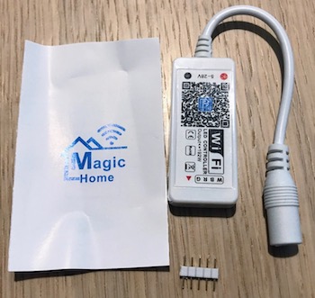
Board is essentially an ESP-12S (or ESP-2M) with necessary voltage converters, little bit of flash, 3 or 4 MOSFETs to drive LED strip (depending on the model), connector for LED strip and optional IR receiver.
Warning
There are new versions of these boards that use an incompatible module, Tasmota cannot be flashed on them! Before anything, make sure your board has a compatible chip.
Module is powered by 12V that is used to power LED strip as well. RGB models are declared as 144W, RGBW models as 192W.
Module comes in (at least) 3 variants: - LC01: RGB, - LC02: RGBW and - LC03: RGB with IR receiver. - LC04: RGBW with IR receiver. - LC05: RGB with Screw-Headers. - LC06: RGBW/WW with Screw-Headers
A different version of this controller with an ESP8285 is documented here The new models comes with the BL602 (RISC-V) and still incompatible as the issue
Serial Connection~
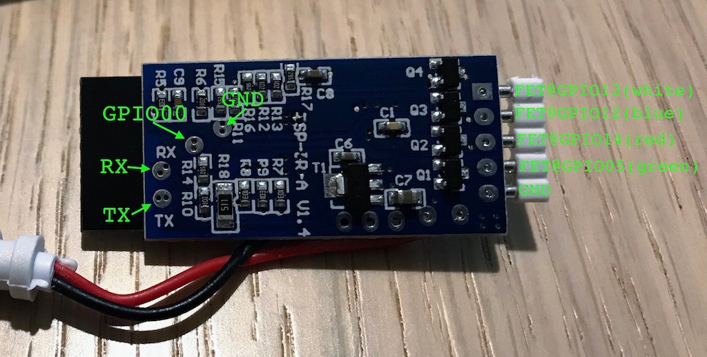
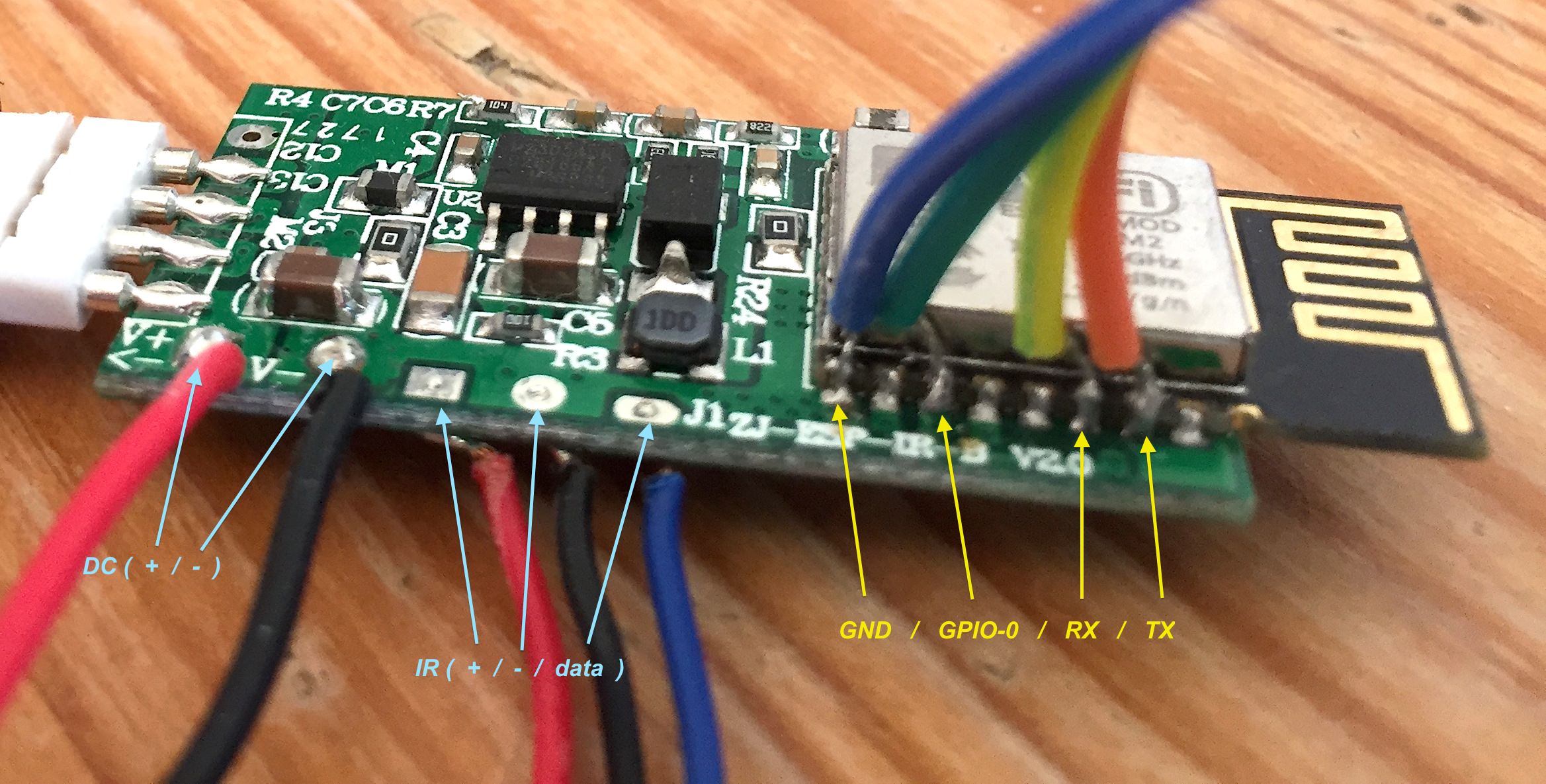
Board has RX, TX, GND and GPIO00 pads exposed on the bottom side of the PCB. You need to solder temporary wires those pads.
You need to power the board while keeping it connected to the programmer.
With all Sonoff boards that work with AC, this is a big no-no that will fry your programmer, your Sonoff and might even get you killed. In this case, you'd be dealing with 12V, so the only thing that matters is to connect the GND of your programmer to GND of the board before you supply the 12V. Not doing so might fry your board and/or programmer, but would definitely not hurt you.
Steps used: 1. Connect your programmer to a breadboard and notice the locations of GND, TX and RX columns. 1. Open the MagicHome controller box and expose bottom side of PCB 1. Solder 4 jumper wires to 4 exposed pads. 1. FIRST connect GND to your programmer (and make sure they are connected well!) 1. Connect RX from the MagicHome to TX on the programmer. TX from the board goes to RX on the programmer. 1. Connect GPIO00 to GND (best to use same column on the breadboard) 1. Connect the 12V power supply to MagicHome. As GPIO00 is connected to GND, board will go into flash mode. Disconnect GPIO00 after few seconds. 1. Upload Tasmota like it would be any other board. 1. Once upload is complete, disconnect power from the MagicHome controller 1. Disconnect RX and TX and then only then GND. GND gets disconnected LAST.
You can then connect the power back to the board and Tasmota should be running on it. Once you verify that board is up and you can access it over the Web, you can unsolder temporary wires and update subsequent firmware versions using OTA.
Configuration~
Some GPIO are preconfigured with the board: - GPIO05 - (PWM2) Green color on the led strip, first pin from the GND - GPIO14 - (PWM1) Red color on the LED strip, second pin from the GND - GPIO12 - (PWM3) Blue color on the LED strip, third pin from the GND
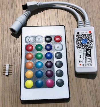
For instructions to setup the 24 Button Remote visit the AL-LC04 device page
Check this for Board Version 2.3 : #1867
Due to variants, you can configure: - GPIO04 - on non-IR boards, it's an open pin you can use for Onewire, button or something else. It might have pull-down resistor and/or bypass capacitor, so please take that into consideration. On IR-enabled boards, IR receiver is connected to this pin, so you can use IRRecv as functionality. - GPIO13 - This pin is not used on RGB board (so you'll leave it as "None"), but on RGBW, it's driving another channel (cold white or warm white) for LED strip.
Variant without Rx/Tx pads:~
-
Using the IRrecv (IR Remote) feature~
If you have a variant with an IR Remote (as per the opening picture), you can use the new rule command to make the remote buttons change the light levels. For example, this rule allows me to turn it on and off, change the brightness, and turn it on to full white:
rule1 on IrReceived#Data=0xFFF807 do power OFF endon on IrReceived#Data=0xFFB04F do WAKEUP endon on IrReceived#Data=0xFF906F do dimmer + endon on IrReceived#Data=0xFFB847 do dimmer - endon on IrReceived#Data=0xFFA857 do color #000000ff endon
Full Set of rules for IR remote~
Each rule can only be 511 characters long, some of the colors below use the built in predefined shortcut color numbers.
rule1 on IrReceived#Data=0xFFF807 do power OFF endon on IrReceived#Data=0xFFB04F do WAKEUP endon on IrReceived#Data=0xFF906F do dimmer + endon on IrReceived#Data=0xFFB847 do dimmer - endon on IrReceived#Data=0xFFA857 do color 12 endon on IrReceived#Data=0xFF9867 do color 1 endon on IrReceived#Data=0xFFD827 do color 2 endon on IrReceived#Data=0xFF8877 do color 3 endon on IrReceived#Data=0xFF28D7 do color  #007FFF endon  on IrReceived#Data=0xFF38C7 do color 4 endon

rule2 on IrReceived#Data=0xFFE817 do color #FF3F00 endon on IrReceived#Data=0xFF48B7 do color #00FF3F endon on IrReceived#Data=0xFF6897 do color #3F00FF endon on IrReceived#Data=0xFF02FD do color 4 endon on IrReceived#Data=0xFF32CD do color #00FFBF endon on IrReceived#Data=0xFF20DF do color #7F00FF endon on IrReceived#Data=0xFF50AF do color #FF7F00 endon on IrReceived#Data=0xFF7887 do color #00BFFF endon on IrReceived#Data=0xFF708F do color #FF00FF endon on IrReceived#Data=0xFFF00F do color #FF003F endon

rule3 on IrReceived#Data=0xFF00FF do scheme 4 endon on IrReceived#Data=0xFF58A7 do scheme 3 endon on IrReceived#Data=0xFF30CF do scheme 2 endon on IrReceived#Data=0xFFB24D do backlog BlinkCount 600; Power 3 endon
rule1 1
rule2 1
rule3 1
The hex codes for the "Data" value come from the data tag when looking at the JSON sent via MQTT. You can also view this data on the Tasmota console screen. From here you can program it to do what ever you want. See here for more details: devices/Rules
