OBI Socket 2~
Supported since version 6.4.1.8 as OBI Socket 2 (61)
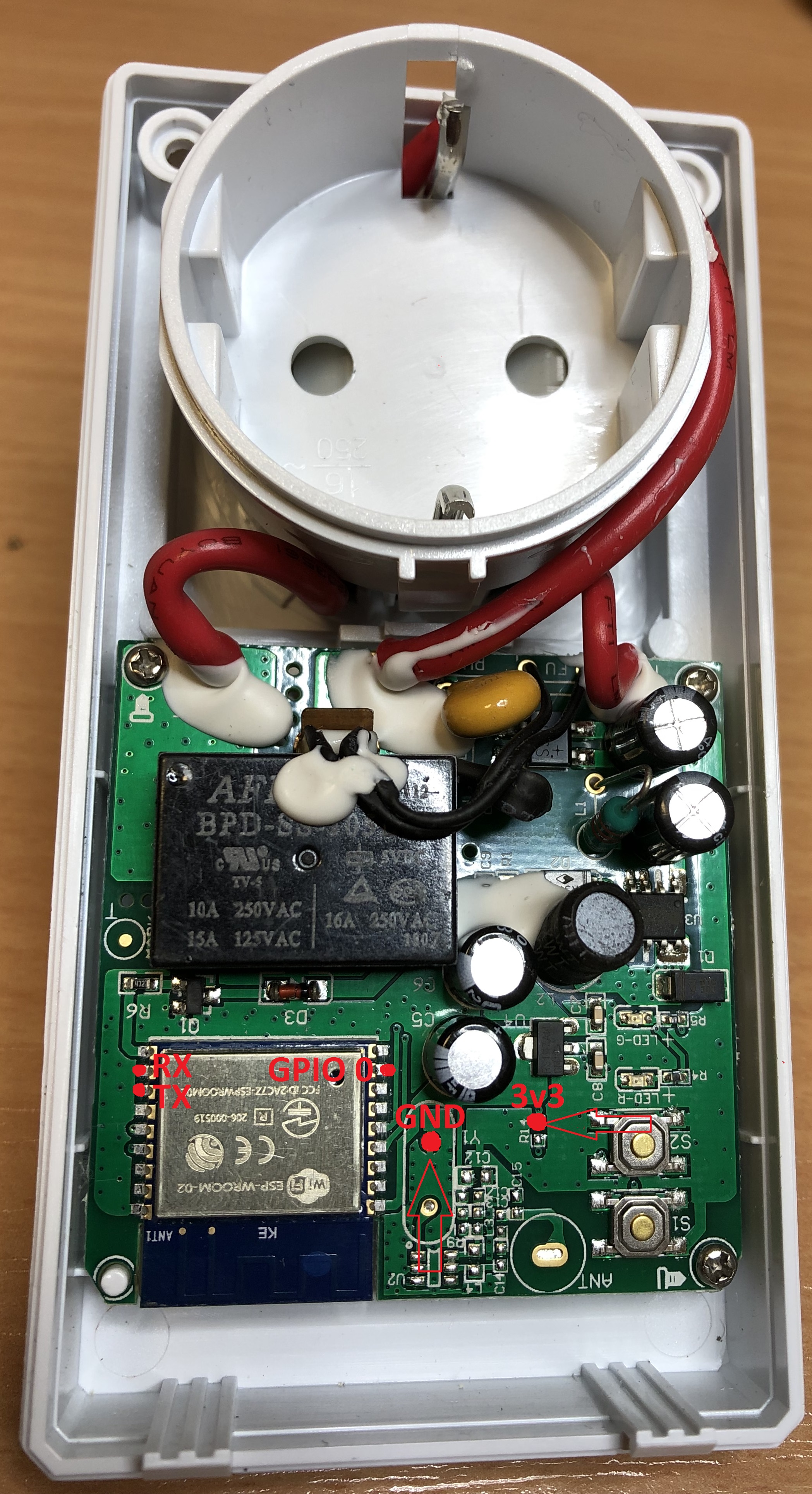
Another cheap socket from the German Hardware Store, based on ESP-WROOM-02 with 2MB Flash. Smaller form factor as the first OBI Socket.

⚠️️ Special Attention ⚠️️~
DO NOT try to flash the module when it is connected to mains AC power. You WILL brick or destroy the device and your computer or USB Port and get electrocutes! Use only a 3.3V USB adapter for flashing
DO NOT CONNECT ANYTHING TO THESE DEVICES!!! (No sensors, no switches, nothing) The OBI Socket 2 has no transformer to isolate the mains voltage. The entire circuit is at mains-level voltage! Only use the device as designed.
One way to flash the module is soldering 4 wires to the RX/TX/3V3/GND pins from the ESP. The PCB has no serial pinout connector. For flashing the module enable the flash mode of the ESP, connect GPIO 0 to GND.
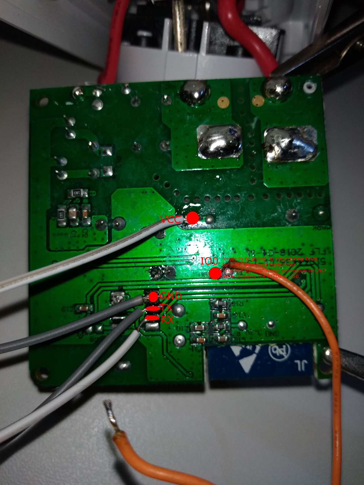
Another way to flash is soldering 4 wires to the bottom side of the PCB as described on https://github.com/mattzzw/obi_socket/wiki/OBI-socket. If you follow that approach of powering the socket with 5V (which enables the relay coil allowing for acoustic feedback) you need to make sure to nevertheless use 3V3 for the actual serial interface to the module!!! This happens to work out very nicely with the popular cheap CH340 USB to Serial TTL adapters which come with a jumper to select between 5V and 3.3V. Setting the adapter to 3.3V by putting the jumper on the 3V3 and VCC pins leaves the 5V pin free. That pin is directly connected to the USB port. So you can just connect the four wires from the socket to the four free pins of the CH340 adapter :-)
If you want the green Wi-Fi LED to work, please use version 6.4.1.8+. You can either use "Obi Socket 2 Type (61)" (with default behaviour "Wi-Fi LED = off" when connected) or use "Generic (18)" for manually override. See issue 4567 for details.
PCB serial pinouts~
PCB serial pinouts (back)~
 ( Note: Same PCB as OBI Socket IP44 (Black) )