RGB Smart Plug 16A
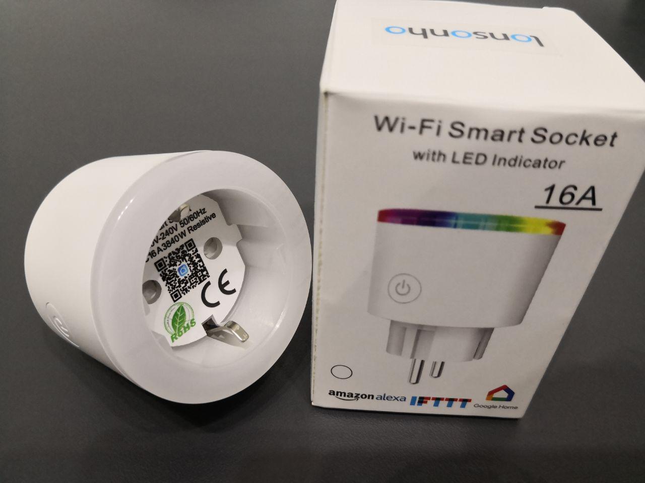 * Aliexpress: Lonsonho Wifi Smart Socket Power Monitor EU 2 Pin * Aliexpress: RGB Smart Plug * amazon.de: Smart Steckdose, Wechsellicht 16A, WLAN Steckdose Wifi Stecker fernbedienbar, Stromverbrauch messen, funktioniert mit Alexa [Echo, Echo Dot] und Google Home, 4 Packs
OTA flashing~
DEVICE IS DIFFICULT TO DISASSEMBLE SO ANY ERRORS WITH FLASHING OR CONFIGURATION CAN EASILY BRICK IT.
DO NOT CONNECT ANY SENSOR TO THESE DEVICES. Only use them as designed.
AS ALWAYS, YOU DO ANY OF THIS AT YOUR OWN RISK.
Device case is glued so recommended way to flash it is using tuya-convert
This method worked for 3 devices that were shipped before December 2019, never paired with Tuya apps and never powered on near open WiFi APs. So they had no chance to download Tuya-Convert updates. It may not work for devices with newer firmware.
Prerequisites~
- You'll need a Linux device with both WiFi capable of running in AP mode and ethernet connection
- Clone/download tuya-convert
- Run
install_prereq.sh
Ubuntu only~
On Ubuntu, it's also necessary to temporary disable WiFi from Network Manager and stop/disable systemd-resolved.
Edit /etc/NetworkManager/NetworkManager.conf and add
[keyfile]
unmanaged-devices=interface-name:wlp2s0
Then run
sudo systemctl restart network-manager.service
sudo systemctl disable systemd-resolved.service
sudo systemctl stop systemd-resolved.service
Start flashing~
- Run
start_flash.shand follow the instructions - Connect any WiFi device to vtrust-flash AP when it asks to and make sure that it gets an IP address. If it doesn't stop and check logs in scripts folder for clues
- Connect socket to mains and long-press the button to enter pairing mode
- Tasmota is included with tuya-convert, follow script's instruction to flash it
- After flashing device should reboot and you should see Tasmota's WiFi AP (Sonoff-xxx). Run
stop_flash.shto shutdown vtrust-flash AP on a machine you used for OTA.
Configuration~
- Connect to Tasmota's AP
- It's extremely important to enter correct WiFi configuration. Button is not on GPIO0 so won't do anything for default Sonoff Basic device profile.
- It's recommended to temporary enter second WiFi with something easy like
SSID: TESTPassword: testtestso you could start that AP and re-configure the device if there are any issues with main WiFi connection. - After it reboots and successfully connects to WiFi configure it as
Blizwolf SHPmodule - Now button and relay should work. Red and Blue LEDs will be used as status LEDs.
RGB Light~
Use this template to configure the device:
{"NAME":"RGB Smart Plug","GPIO":[37,0,39,0,38,134,0,0,131,17,132,21,0],"FLAG":0,"BASE":45}
For older versions:
Complete RGB support requires building slightly custom Tasmota. Edit sonoff/sonoff_template.h and replace "BlitzWolf SHP" configuration with the following:
  { "BlitzWolf SHP",   // BlitzWolf BW-SHP2 and BW-SHP6 (ESP8285 - BL0937 or HJL-01 Energy Monitoring)
                       // https://www.banggood.com/BlitzWolf-BW-SHP2-Smart-WIFI-Socket-EU-Plug-220V-16A-Work-with-Amazon-Alexa-Google-Assistant-p-1292899.html
                       // https://www.amazon.de/Steckdose-Homecube-intelligente-Verbrauchsanzeige-funktioniert/dp/B076Q2LKHG/ref=sr_1_fkmr0_1
                       // https://www.amazon.de/Intelligente-Stromverbrauch-Fernsteurung-Schaltbare-Energieklasse/dp/B076WZQS4S/ref=sr_1_1
                       // https://www.aliexpress.com/store/product/BlitzWolf-BW-SHP6-EU-Plug-Metering-Version-WIFI-Smart-Socket-220V-240V-10A-Work-with-Amazon/1965360_32945504669.html
     GPIO_USER,        // GPIO00 Red Led (1 = On, 0 = Off)
     GPIO_USER,        // GPIO01 Serial RXD and Optional sensor
     GPIO_USER,        // GPIO02 Blue Led (1 = On, 0 = Off)
     GPIO_USER,        // GPIO03 Serial TXD and Optional sensor
     GPIO_USER,        // GPIO04
     GPIO_HJL_CF,      // GPIO05 BL0937 or HJL-01 CF power
     0, 0, 0, 0, 0, 0, // Flash connection
     GPIO_NRG_SEL_INV, // GPIO12 BL0937 or HJL-01 Sel output (0 = Voltage)
     GPIO_KEY1,        // GPIO13 Button
     GPIO_NRG_CF1,     // GPIO14 BL0937 or HJL-01 CF1 current / voltage
     GPIO_REL1,        // GPIO15 Relay (0 = Off, 1 = On)
     0, 0
  },
[[https://raw.githubusercontent.com/wiki/Astr0/Sonoff-Tasmota/images/lonsonho16a/config.png|Configuration]]
RGB and dimming should work now.
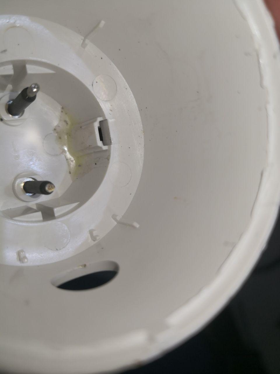
Disassembling the device~
This is not recommended. Do it only if you have to or just buy a new one. The device is hard to open and may be damaged. Components inside may have mains charge and electrocute you even if powered off. Do it at your own risk.
One of my devices had a hardware issue - constantly losing WiFi, rebooted when wiggled in power socket, rebooted every few seconds on 1250W load, sometimes just hanged and not responded even to the button. Since it wasn't usable at all I tried to fix it. The reason was broken steel input pole inside(what?? how?? WTF??) that was making weak contact, couldn't fix it reliably.
- Unbend earth connections on the bottom to make them straight.
- Use a sharp knife to slice through glue between RGB ring and the case. Requires quite a lot of force and time. RGB ring may break in places where glue is stronger than the plastic.
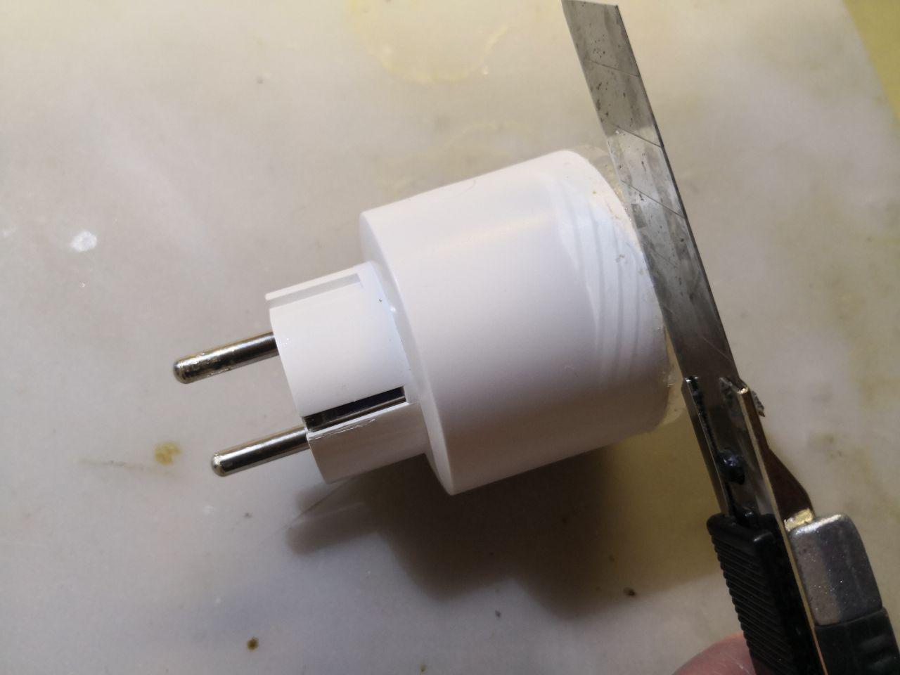
- Use a screwdriver to pry the case open.
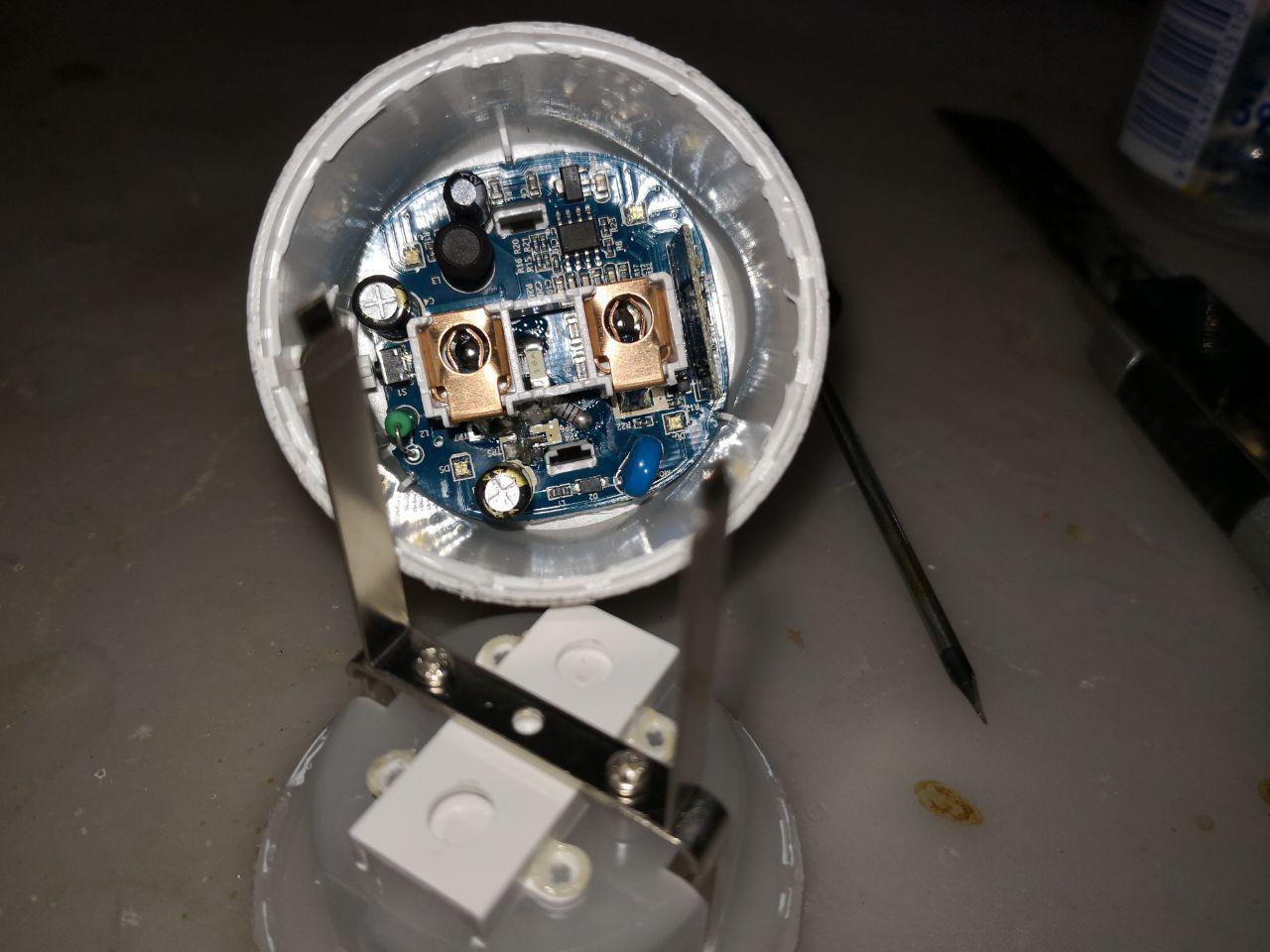
- Remove button cap
- Desolder output connections, try not to melt any plastic. Remove support plastic with a screwdriver, it's held to the PCB by two clips.
- Desolder input poles. This is tricky since there's a lot of solder. I've removed as much of it as possible with desoldering pump, then melted the solder and rotated the poles with pliers while it cooled. Poles are made of steel and steel don't accept solder well.
-
Remove the PCB by lifting it up. It's glued to the case on the bottom by the relay and held tight with input poles so it requires some force. Also, it's not easy to grab the PCB. I've used dip removing tweezers, holding PCB by holes for the earth connectors.
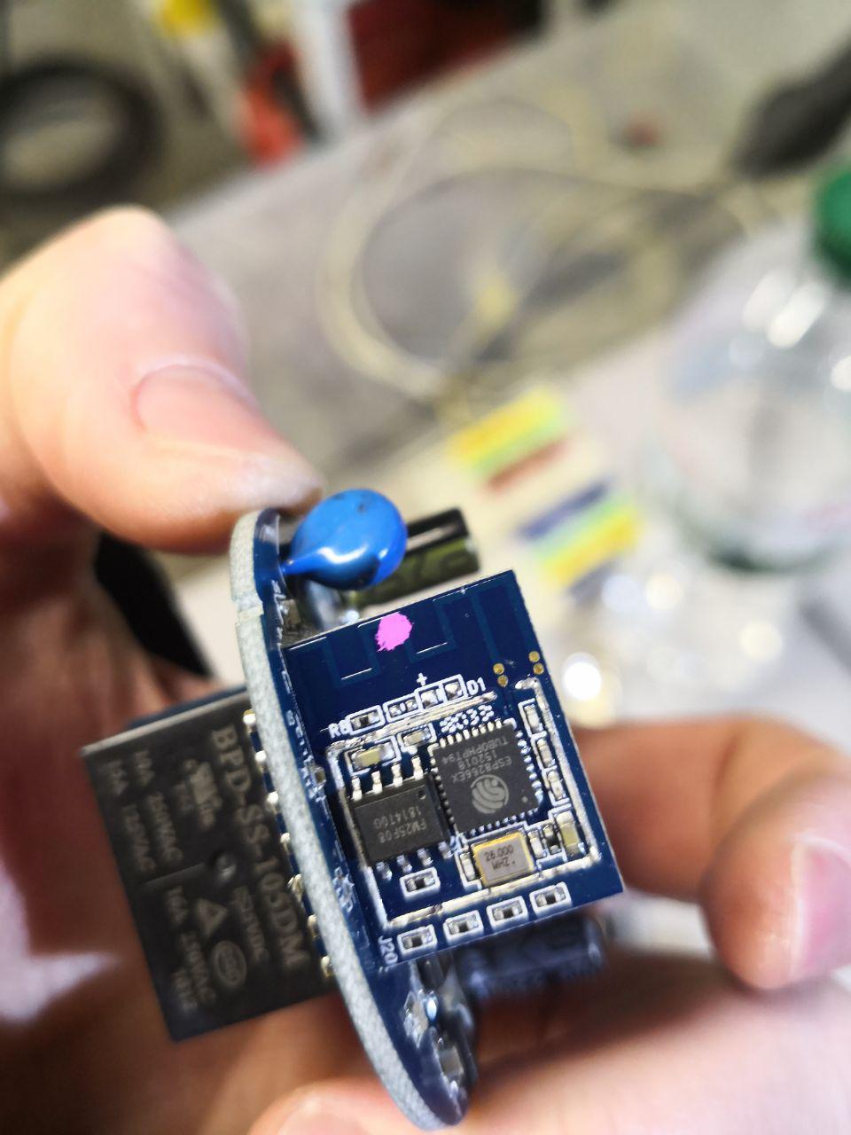
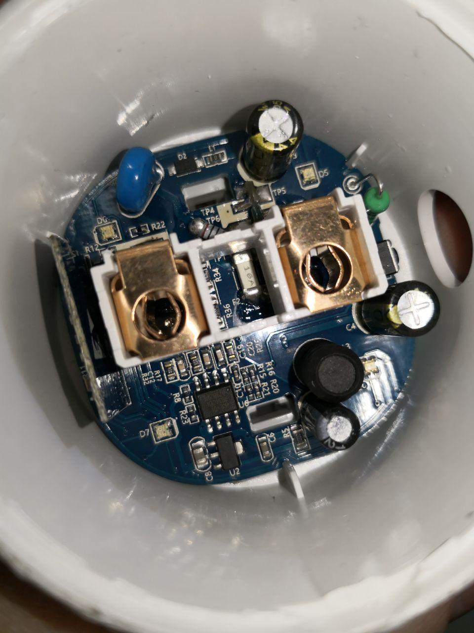
I figured out the pinout for flashing the device:

-
Before assembling it back remove as much solder as possible from input and output pole pads. The device fits together very tight, so everything should be perfectly in place. Don't forget to glue the case back.
Alternative to disasselmy: Drilling two holes.~
_With all this information at hand it is also possible to drill two simple holes into the case to get to the necessary contact pads. I recommend a 6mm drill, carfully drill trough the case at he center of the ledge from the high power side opposite the power button. See pictures. Now you can solder on a few temporary flash cables. Don't forget to pull IO0 to GND to get into flash mode.
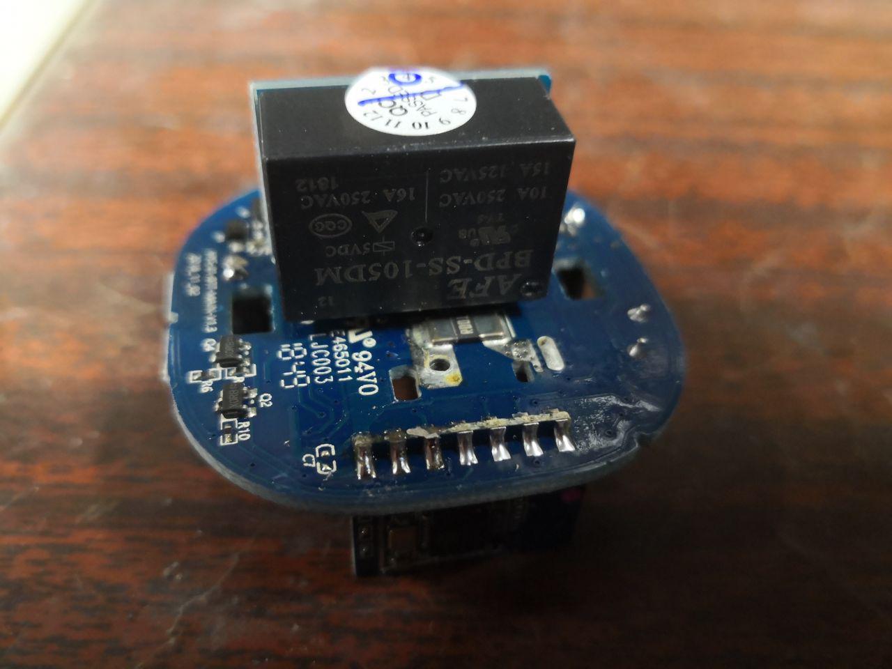
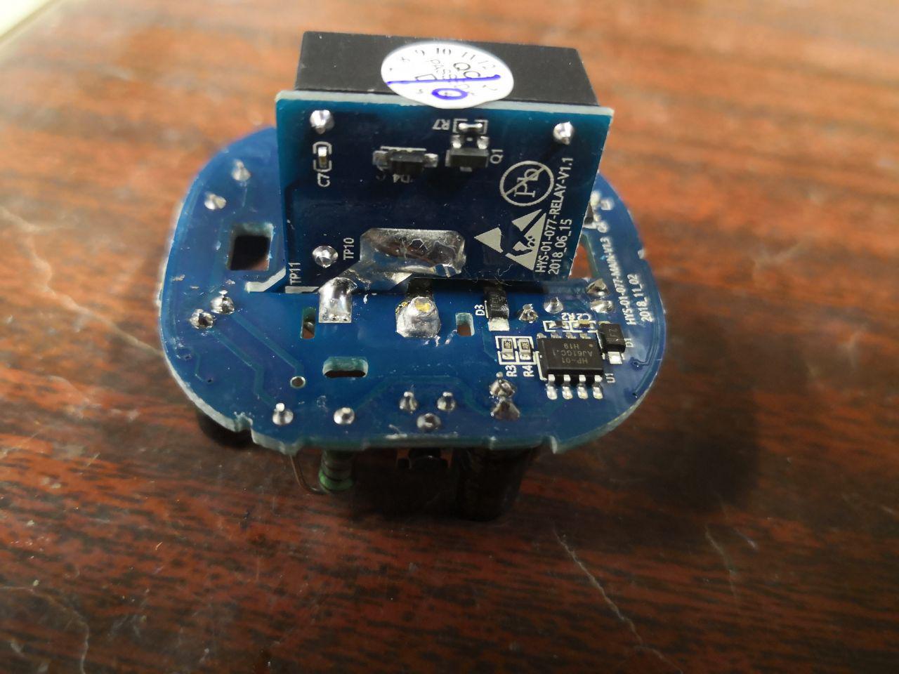
Few observations: * It has ESP8266EX with FM25F08 8Mbit flash. The module has lots of connections, some of them have only pads without tracks on the main board. High chances to find RX and TX there. Obviously, there should be VCC and GND to power up the module. * Uses HJL-01 with a shunt for power monitoring, so every mains power track that looks like it should be covered with solder but is not, probably should be covered with solder :) * It has 4 RGB LEDs. GPIO00-Red, GPIO02-Blue, GPIO04-Green * AFE BPD-SS-105DM 16A 250VAC relay * 16A SMD fuse for mains input * Something that's probably another fuse marked F1 for low-voltage circuitry power * Low-voltage part is not galvanically insulated from mains * There's "QC Passed" sticker on the relay