SP108E HardwareAnalysis
So far I analyzed it is equipped with these chips:
- ESP-12F
- STM32F-030C8T (Cortex M0)
- Winbond 25Q32 (EEPROM)
- 74HC245
- XL1509 3.3E1 (Step down regulator)
- RX/TX of STM is connected to ESP.
- 74HC245 buffers the outputs
ESP is connected to the STM RX/TX pins. No other connections seen. We can assume there is some firmware in the STM that does the low level connection to the LEDs.
Question is how does the ESP communicate with the STM and what exactly does the STM at all. But we can mod the hardware so the ESP can talk to the LEDs.
I made some pictures with phone and microscope.
PCB

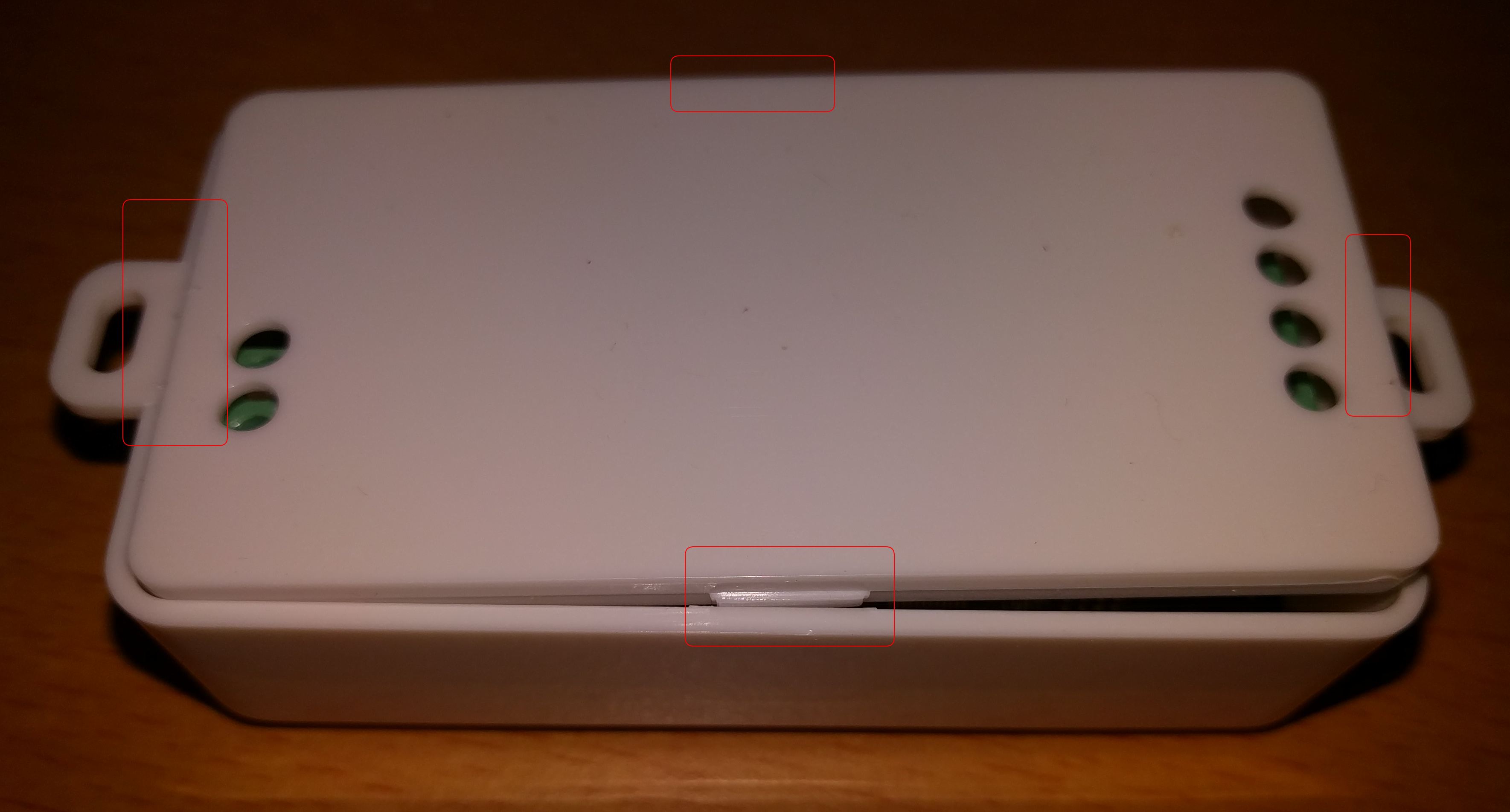
Open the housing, see the red marks for the holders)
RX/TX connection ESP to STM

STM32F0

EEPROM

Pins lead to the STM32F0 (Firmware flash? Debug?)

ESP-12 and its pins


Buffer chip 74HC245

Traces on bottom side from STM to HC245 (actually R3 and R4)

Known differences to the 2nd gen
The following picture shows the pcb of the 2nd generation of the SP108E.

The ESP12F was replaced to a proprietary ESP8285 pcb. Fortunately the pinout is printed on the back of the pcb so we can use it to connect the cables for flashing. As the pcb were already soldered out for taking the following picture it was flashed in this unmounted state. It should work as well while the ESP is soldered. Pay attention to the information below.

The STM32F0 was replaced through a Geehy APM32F030C8T6 ARM-Cortex M0 microcontroller. At least the reset pin is at the same place. So the hardware modification of the first gen can also be applied.
For the hardware mod to make it working without the STM32F0/Geehy, there are several ways:
1. Cut traces and add wires~
We need to break one of the traces on the bottom of the PCB. Then connect GPIO4 of ESP-12 with R4. Also RX/TX connection between STM32F0 and ESP-12 need to be broken up.
2. Hold STM32F0 in reset~
This is the simpler method, no cuts on the PCB required, just two additional wires. - NRST of STM32F0 to GND - IO4 of ESP-12 to R4
See here for details.
Flashing prohibited (not anymore with a cut in the PCB)~
Major problem is that IO0 is directly connected to VCC, so we cannot bring ESP-12 into flash mode. This is for the older rev of the PCB and showing the same physical device seen in my very first posts a few years ago.
After removing the ESP-12, the trace was visible and now it is easy to see where to cut the PCB. See the "cut here" in blue letters. I also sketched the VCC-trace in red. After the cut cut you can connect the IO0 to GND for reflashing. Later you need to connect back to VCC.
