SeedStudio SenseCAP Indicator D1~
The device is a 4-Inch Touch Screen IoT development platform powered by ESP32S3 & RP2040. It has variants with LoRa support, and Air Quality support.
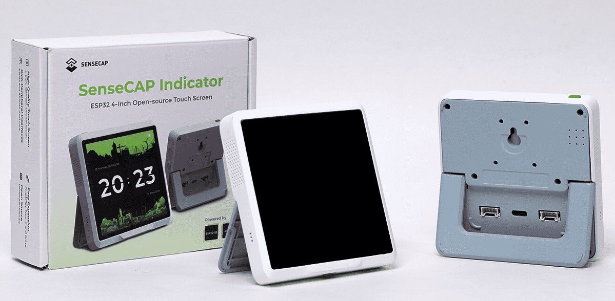
Link to purchase the device SeedStudio web site
There are variants, all sharing the following features:
- ESP32S3 with 8MB Flash and 8MB PSRAM
- 4 inch 480 x 480 pixels display, ST7701 controller, connected in parallel 8 bits mode to ESP32S3 for maximum display speed
- Capacitive Touchscreen, FT5x06 controller
- SD Card connector
- Dual I2C Groove connectors
- Dual USB-C connectors below and in the back of the device
- Buzzer MLT-8530, Resonant Frequency:2700Hz
- Also contains a RP2040 MCU, Dual ARM Cortex-M0+ up to 133MHz, 2MB of Flash
We will focus below on the "SenseCAP Indicator D1L" which includes:
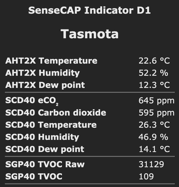
- internal SGP41 tVOC Air Quality Sensor (Range: 0-40000ppm, Accuracy: 400ppm - 5000ppm ±(50ppm+5% of reading))
- internal SCD40 CO2 Carbon Dioxid Sensors (Range: 1-500 VOC Index Points)
- external AHT20 Temperature and Humidity sensor (Range: -40 ~ + 85 ℃/± 0.3 ℃; 0 ~ 100% RH/± 2% RH (25 ℃))
ESP32S3 build~
The device requires a self-compile with the following options:
- Compile with an environment that uses
board = esp32s3-qio_opi_120, which enables Quad SPI Flash and Octal SPI PSRAM at 120MHz. - Enable the following options:
USE_SDCARD,USE_I2C_SERIAL,USE_AHT2x,USE_SGP4X,USE_SCD40,USE_I2C,USE_SPI,USE_LVGL,USE_DISPLAY_LVGL_ONLY,USE_DISPLAY,USE_UNIVERSAL_TOUCH,USE_UNIVERSAL_DISPLAY
In file platformio_override.ini, add the following section and select :
[env:tasmota32s3-qio_opi_120-SenseCap_D1]
; device needs >= 8MB Flash!!
extends                     = env:tasmota32_base
board                       = esp32s3-qio_opi_120
board_build.partitions      = partitions/esp32_partition_app3904k_fs3392k.csv
build_flags                 = ${env:tasmota32_base.build_flags}
                              -DUSE_BERRY_ULP
                              -DFIRMWARE_LVGL
                              -DUSE_LVGL_OPENHASP
                              -DUSE_I2C_SERIAL
                              -DUSE_AHT2x
                              -DUSE_SGP4X
                              -DUSE_SCD40
                              -DOTA_URL='""'
and compile with:
default_envs =
; *** Uncomment the line(s) below to select version(s)
    tasmota32s3-qio_opi_120-SenseCap_D1
Auto-configuration~
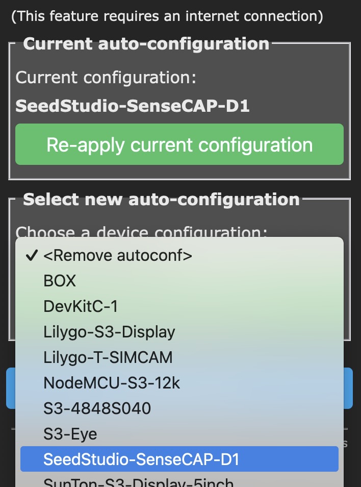
For easy configuration, select "Configuration" then "Auto-configuration". Select "SeedStudio-SenseCAP-D1" in the dropdown and click on "Apply configuration". The device will download the configuration (internet connection is required) and reboot twice.
Configure GPIOs and LVGL Display~
If you used Auto-Configuration, you can skip this section. This is a manual alternative to auto-configuration.
Use:
Template {"NAME":"SenseCAP Indicator D1","GPIO":[0,0,0,0,0,0,0,0,0,0,0,0,0,0,0,0,0,0,0,11488,11520,0,6210,0,0,0,0,32,641,609,0,1,1,1,0,1,0,0],"FLAG":0,"BASE":1}
Module 0
Add the following content in display.ini on the device file-system:
:H,ST7701,480,480,16,RGB,18,17,16,21,45,15,14,13,12,11,10,9,8,7,6,5,4,3,2,1,0,6
:V,1,10,8,50,1,10,8,20,0
:S,2,1,1,0,40,20
:IS,41,48,-1,-1
FF,5,77,01,00,00,10
C0,2,3B,00
C1,2,0D,02
C2,2,31,05
C7,1,04
CD,1,08
B0,10,00,11,18,0E,11,06,07,08,07,22,04,12,0F,AA,31,18
B1,10,00,11,19,0E,12,07,08,08,08,22,04,11,11,A9,32,18
FF,5,77,01,00,00,11
B0,1,60
B1,1,32
B2,1,07
B3,1,80
B5,1,49
B7,1,85
B8,1,21
C1,1,78
C2,A1,78
E0,3,00,1B,02
E1,B,08,A0,00,00,07,A0,00,00,00,44,44
E2,C,11,11,44,44,ED,A0,00,00,EC,A0,00,00
E3,4,00,00,11,11
E4,2,44,44
E5,10,0A,E9,D8,A0,0C,EB,D8,A0,0E,ED,D8,A0,10,EF,D8,A0
E6,4,00,00,11,11
E7,2,44,44
E8,10,09,E8,D8,A0,0B,EA,D8,A0,0D,EC,D8,A0,0F,EE,D8,A0
EB,7,02,00,E4,E4,88,00,40
EC,2,3C,00
ED,10,AB,89,76,54,02,FF,FF,FF,FF,FF,FF,20,45,67,98,BA
36,1,10
FF,5,77,01,00,00,13
E1,1,E4
FF,5,77,01,00,00,00
21,0
3A,1,60
11,80
29,80
:B,120,02
:UTI,FT5x06,I2,48,-1,-1
RD A8
CP 11
RTF
RD A3
CP 64
RTF
RT
:UTT
RDM 00 16
MV 2 1
RT
:UTX
MV 3 2
SCL 480 -1
RT
:UTY
MV 5 2
SCL 480 -1
RT
#
Using Air Quality Sensors~
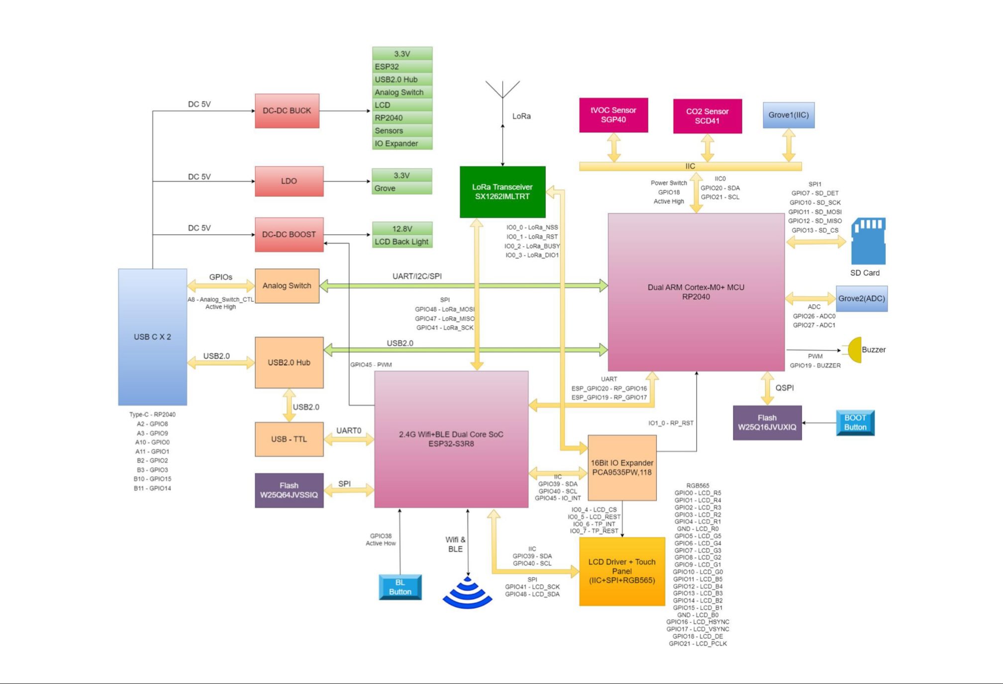
According to the schematics, ESP32S3 is directly connected in I2C to the FT5x06 TouchScreen Controller, and to the PCA8535 IO Expander. The SCD40, SGP41 and AHT20 are connected in I2C to the RP2040 MCU so out of reach of Tasmota. For this, we have added the I2C_SERIAL interface which allows to access remote I2C devices via a UAR interface using the same Serial protocol as NXP SC18IM704 chip.
To make it accessible from native I2C drivers, the I2C Serial driver must use bus 1, and the I2C bus connected to ESP32S3 must use I2C bus 2.
Now you need to flash the RP2040 and use a simple Micropython script to bridge the UART to I2C bus.
Flashing and configuring RP2040~
Step 1. Flash Micropython~
To flash the RP2040, you need to insert a pin in the "reset" small hole, and power-up the device while keeping the Reset button pushed. You can then release the Reset button.
RP2040 boots in flash mode, and shows a USB disk. Simply download the latest RPI Pico Micropython firmware (file ending with .uf2) from the official Micropython site. This was tested with RPI_PICO-20241025-v1.24.0.uf2.
Step 2. Use Thonny~
For easy setup, download and install Thonny:
- Launch Thonny
- Connect to the RP2040: click on the lower right corner and select
MicroPython (RP2040) - Copy and paste the Micropython code from below
- Click on "Save", select "RP2040 Device" and choose "main.py" as a filename
- You can hit the "Run Current Script" button (green arrow) to see the script running
- The script will automatically run at power on
Here is how it should look like: 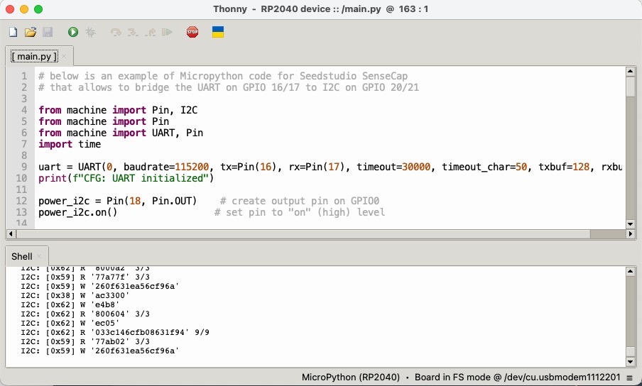
Step 3. MicroPython code for RP2040~
# below is an example of Micropython code for Seedstudio SenseCap
# that allows to bridge the UART on GPIO 16/17 to I2C on GPIO 20/21

from machine import Pin, I2C
from machine import Pin
from machine import UART, Pin
import time

uart = UART(0, baudrate=115200, tx=Pin(16), rx=Pin(17), timeout=30000, timeout_char=50, txbuf=128, rxbuf=128)
print(f"CFG: UART initialized")

power_i2c = Pin(18, Pin.OUT)    # create output pin on GPIO0
power_i2c.on()                 # set pin to "on" (high) level

i2c = I2C(0, scl=Pin(21), sda=Pin(20), freq=400_000, timeout=1000)

# print(f"I2C: scan {i2c.scan()}")

# i2c_stat:
# 0: no error
# 1: I2C_NACK_ON_ADDRESS
# 2: I2C_NACK_ON_DATA
# 3: I2C_TIME_OUT
i2c_stat = 0
def set_i2c_stat(v):
    global i2c_stat
    i2c_stat = v

def get_i2c_stat():
    global i2c_stat
    return i2c_stat


def ignore_until_P():
    # read uart until none left or 'P' reached
    # return last unprocessed char or None
    while True:
        c = uart.read(1)
        if c is None:
            return None # end of receive
        if c == b'P':
            cur_char = None
            return None # end reached

def process_cmd_start():
    # return last unprocessed char or None
    addr_b = uart.read(1)
    if addr_b is None:  print("start: no address sent"); return None
    addr = addr_b[0] >> 1
    is_write = not bool(addr_b[0] & 1)
    len_b = uart.read(1)
    if len_b is None:  print("start: no length sent"); return None
    len_i = len_b[0]
    cmd_next = None
    # dispatch depending on READ or WRITE
    if is_write:
        payload_b = bytes()
        if len_i > 0:
            payload_b = uart.read(len_i)
            if len(payload_b) < len_i:
                print(f"start: payload {payload_b} too small, expected {len_i} bytes")
                return None
        stop_bit = False
        cmd_next = uart.read(1)
        if cmd_next == b'P':
            stop_bit = True
        try:
            set_i2c_stat(0)
            acks_count = i2c.writeto(addr, payload_b, stop_bit)
            #print(f"{acks_count=} {len_i=}")
            if acks_count < len_i:
                set_i2c_stat(2)
            else:
                print(f"I2C: [0x{addr:02X}] W '{payload_b.hex()}'")
            #print(f"{acks_count=} {len_i=} {get_i2c_stat()=}")
        except Exception as error:
            #print(f"{error=}")
            set_i2c_stat(1)    # I2C_NACK_ON_ADDRESS
        # if 'S' is followed, return to main loop
        if cmd_next == b'S':
            return cmd_next
    else:
        # read
        payload_b = b''
        #print(f"read: [0x{addr:02X}] {len_i}")
        try:
            set_i2c_stat(0)
            payload_b = i2c.readfrom(addr, len_i, True)
            print(f"I2C: [0x{addr:02X}] R '{payload_b.hex()}' {len(payload_b)}/{len_i}")
            uart.write(payload_b)
        except Exception as error:
            print(f"I2C: error while reading from 0x{addr:02X} len={len_i} error '{error}'")
            set_i2c_stat(1) # I2C_NACK_ON_ADDRESS
            return None
    return None


def process_cmd_stop():
    # return last unprocessed char or None
    return None                         # do nothing

def process_cmd_read():
    # return last unprocessed char or None
    # we accept only 1 register for now
    reg = uart.read(1)
    if reg is None: print("read: no register sent"); return None
    cmd_next = uart.read(1)
    if cmd_next is None or cmd_next != b'P': print("read: unfinished command"); return None
    #
    reg = reg[0]  # convert to number
    if reg == 0x0A: # I2CStat
        uart.write(int.to_bytes(get_i2c_stat() | 0xF0))
    else:
        uart.write(int.to_bytes(0x00))
    return None

def process_cmd_write():
    # return last unprocessed char or None
    print("I2C: ignore 'W' commmand")
    return ignore_until_P()

def process_cmd_version():
    ignore_until_P()
    uart.write(b'Tasmota I2C uart bridge 1.0\x00')
    return None

def process_cmd_ignore():
    # return last unprocessed char or None
    return ignore_until_P()

def process_discard():
    # discard all bytes in input
    # return last unprocessed char or None
    while uart.any() > 1:
        uart.read(uart.any())
    return None

def run():
    cmd = None
    while True:
        if cmd is None and uart.any() > 0:
            cmd = uart.read(1)
        if cmd is None:
            time.sleep(0.01)
        else:
            #print(f"SER: received cmd {cmd}")
            if cmd == b'S':
                cmd = process_cmd_start()
            elif cmd == b'P':
                cmd = process_cmd_stop()
            elif cmd == b'R':
                cmd = process_cmd_read()
            elif cmd == b'W':
                cmd = process_cmd_write()
            elif cmd == b'V':
                cmd = process_cmd_version()
            elif cmd == b'I' or cmd == b'O' or cmd == b'Z':
                cmd = process_cmd_ignore()
            else:
                cmd = process_discard()

run()
Step 4. Wrap-up~
Reboot and you should the sensors working.
For reference, here are the boot logs with Seriallog 3:
00:00:00.251 CMD: Fall back to serial port, no SOF packet detected on USB port
00:00:00.251 HDW: ESP32-S3 v0.2 (PSRAM)
00:00:00.262 UFS: FlashFS mounted with 4380 kB free
00:00:00.267 CFG: Loaded from File, Count 386
00:00:00.273 QPC: Count 1
00:00:00.274 CFG: CR 362/699, Busy 0
00:00:00.275 I2C: Bus2 using GPIO40(SCL) and GPIO39(SDA)
00:00:00.290 CFG: No '*.autoconf' file found
00:00:00.295 BRY: Berry initialized, RAM used 6578 bytes
00:00:00.298 BRY: No 'preinit.be'
00:00:00.305 DSP: File descriptor used
00:00:01.236 UTI: FT5x06 initialized
00:00:01.236 DSP: ST7701 initialized
00:00:02.239 I2C: I2C serial configured on GPIO TX 19 / RX 20 for bus 1
00:00:02.260 I2C: I2C serial initialized
00:00:02.261 SRC: Restart
00:00:02.263 Project tasmota - Tasmota Version 14.3.0.4(tasmota)-3_1_0(2024-11-07T22:41:20)
00:00:02.275 LVG: Allocating buffer1 112 KB in main memory (flushlines 120)
00:00:02.280 LVG: LVGL initialized
00:00:02.405 I2C: AHT2X found at 0x38
00:00:03.069 SCD40 serial nr 0x2FC1 0x5B07 0x3BCF
00:00:03.081 I2C: SCD40 found at 0x62
00:00:03.116 SGP4X serial nr 0x0 0x57F 0x84F1
00:00:03.137 SGP4X features: 0x3240
00:00:03.137 I2C: SGP4X found at 0x59
Internals~
SeedStudio does not provide the detailed schematics, but still provides an overview of GPIO connection:
