Shelly 1PM~
The Shelly 1PM is supported from Tasmota 6.5.0.10 using a template.
⚠️️Special Shelly Attention⚠️️~
DO NOT CONNECT ANYTHING TO ANY GPIOs OF THESE DEVICES!!! (No sensors, no switches, nothing)
The GPIOs on the Shelly are connected to AC power! Only use a Shelly as designed.
Do not connect AC power and the serial connection at the same time The GND connection of the Shelly is connected to the live AC wire. Connecting serial with your PC will fry your PC.
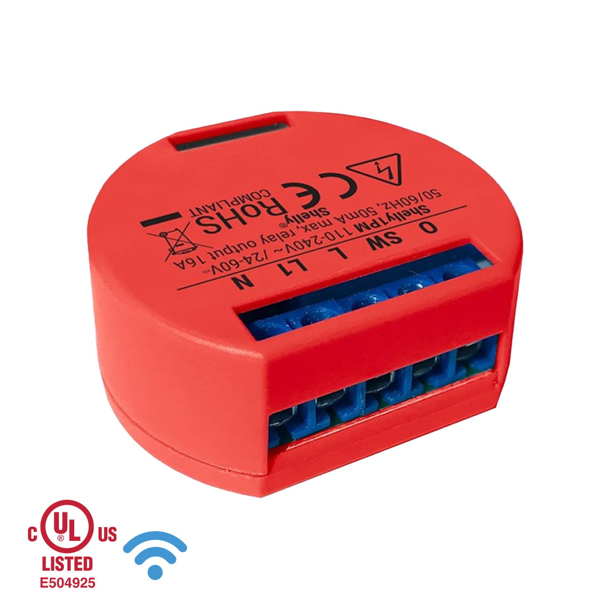
An ESP8266 with 2MB flash single relay device 42mm "round" in size.
Serial Flashing~
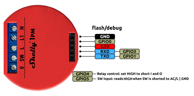
Shelly 1PM comes with a partially exposed programming/debug header which can be used to flash Tasmota on the device. A USB-to-UART adapter is needed as well as a reliable 3.3V with at least 350 mA drive capability. The following diagram shows the device pinout.
Template~
{"NAME":"Shelly 1PM","GPIO":[56,0,0,0,82,134,0,0,0,0,0,21,0],"FLAG":2,"BASE":18}
Calibration~
Tasmota will disable serial logging after a restart as the communication between Tasmota and the Energy Monitoring chip is using the same serial interface. Make sure not to enable SerialLog as it will interfere with the Energy Monitoring functionality.
To calibrate the Energy monitoring feature connect a known load and execute the commands shown below. Assumed an AC voltage of 240V, a resistive load of 60W and a line frequency of 50Hz. With a load of 60W the current should be 60W / 240V = 0.25A.
FrequencySet 50.000
PowerSet 60.00
VoltageSet 240.0
CurrentSet 250.0