Shelly 2.5~
The Shelly 2.5 is supported from Tasmota 6.5.0.8 using a template.
⚠️️Special Shelly Attention⚠️️~
DO NOT CONNECT ANYTHING TO ANY GPIOs OF THESE DEVICES!!! (No sensors, no switches, nothing) The GPIOs on the Shelly are connected to AC power! Only use a Shelly as designed.
Do not connect AC power and the serial connection at the same time The GND connection of the Shelly is connected to the live AC wire. Connecting serial with your PC will fry your PC.
Warning (April 10, 2019): This appears to affect a percentage of their entire first run production. Check your device before powering it on.
An ESP8266 with 2MB flash dual relay device with Energy Monitoring. Slightly smaller than the original Shelly 2.
Serial Connection~
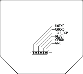
The Shelly 2.5 model comes with a partially exposed programming/debug header which can be used to flash Tasmota on the device. A USB-to-UART adapter is needed as well as a reliable 3.3V with at least 350 mA drive capability. The following diagram shows the device pinout and power source voltage selection jumper.
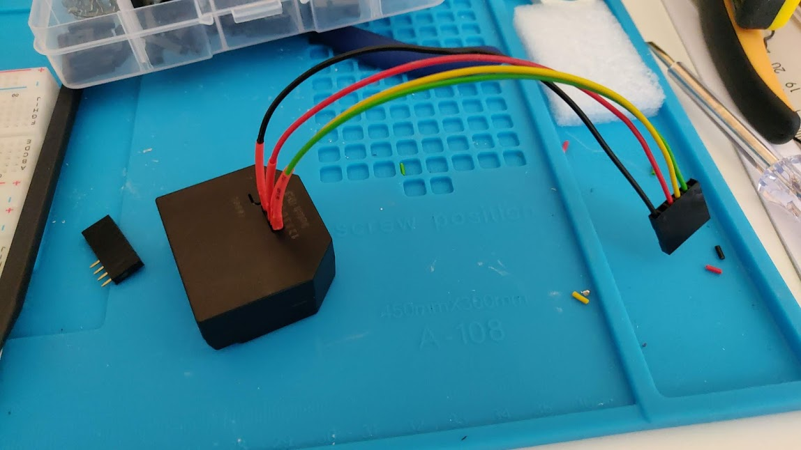
The onboard connector is 1.27mm raster with 1mm diameter holes. Normal Dupont cables won't fit. To avoid damaging the pcb, use either a stripped 24 AWG Ethernet cable and breadboard as an adapter, or female header socket legs (see image below). The legs of a female header socket fit nicely. Solder them to custom-crimped Dupont wires for use with your USB-to-UART adapter. These often come with Wemos D1 Mini boards in multiple lengths.

Otherwise you could simply buy an adapter that converts Dupont to 1.27mm raster at tindie
Template~
Tasmota 6.5.0.8 and higher supports Shelly 2.5
| GPIO | Component |
|---|---|
| 0 | LED1i |
| 2 | Button1 |
| 4 | Relay1 |
| 5 | Switch2n |
| 12 | I2C SDA |
| 13 | Switch1n |
| 14 | I2C SCL |
| 15 | Relay2 |
| 16 | ADE7953 IRQ |
| A0 | Internal Temperature |
{"NAME":"Shelly 2.5","GPIO":[56,0,17,0,21,83,0,0,6,82,5,22,156],"FLAG":2,"BASE":18}
Energy metering is done by an ADE7953 chip connected via I2C and IRQ on GPIO16.
If you connect momentary switches, use the following template: {"NAME":"Shelly 2.5 (buttons)","GPIO":[56,0,19,0,21,127,0,0,6,126,5,22,156],"FLAG":2,"BASE":18} Button1 and Button2 are assigned to the SW1 and SW2 external inputs. Button3 is the button on the back of the device next to the pin header and you can optionally assign the behaviour you want using rules.
If you want the buttons to respond instantly, go to the console and type SetOption13 1. But, if you want press/double press/hold functionality, run instead Backlog SetOption1 1; SetOption11 1; SetOption32 20 to enable all three states and set hold time of 2 seconds. Use SetOption32 to set another hold time.
If you want to see Voltage and Frequency also when the relays are off, use SetOption21 1
Flash mode~
To be able to flash the Tasmota firmware you need to get into flash mode. Therefore connect a wire from GPIO0 to ground. For further information have a look at programming mode.
Calibration~
Tasmota will disable serial logging after a restart as the communication between Tasmota and the Energy Monitoring chip is using the same serial interface. Make sure not to enable SerialLog as it will interfere with the Energy Monitoring functionality.
To calibrate the Energy monitoring feature connect a known load and execute the commands shown below. Assumed an AC voltage of 240V, a resistive load of 60W and a line frequency of 50Hz. With a load of 60W the current should be 60W / 240V = 0.25A.
FrequencySet 50.000
PowerSet 60.00
VoltageSet 240.0
CurrentSet 250.0
Use rules to control shutter endpoints~
As the Shelly 2.5 contains energy monitoring you can use rules to power off the shutter when too much current is drawn at the end point. This rule will power off both directions when the current becomes greater than 600mA. Before you activate the rule, let your shutter move and pay attention to the current value in the WebGUI. Note your value and add 0.050 to your value. After that, you change the value for the rule.
Eg.: Your Value = 0.520 + 0.050 = 0.570
energy#current[X]>0.570
rule1 on energy#current[2]>0.600 do shutterstop endon on energy#current[1]>0.600 do shutterstop endon
rule1 1
rule1 5
Use Shelly 2.5 device for Blinds and Shutters~
Further Information: Blinds and Shutters
Ghost switching~
The Shelly 2.5 inputs appear to be notoriously susceptible to interference. Therefore ghost switching can happen if the wires are long (>1m / 3ft). If you experience this issue, you might want to experiment with the switch debounce delay. It is set to 50 milliseconds by default.
Use command SwitchDebounce 100 to change it to a less sensitive value, which might work better. The value can be set up to 1000 milliseconds.
Some issues were reported for this topic - search query
Overheating~
Due to the built-in temperature sensor, it is possible to switch off the relays when a certain temperature is exceeded. The limit for the original Shelly firmware seems to be around 95 ° C. Source
The ambient temperature according to the manufacturer is between - 40 ° C up to 40 ° C
Even at temperatures within this range, a significantly higher temperature can occur when installed behind switches or in walls. There are reports that temperature-related shutdowns occur at high loads. A standby temperature between 30-60 ° C seems normal. An overtemperature threshold is implemented in the Tasmota firmware.
Note
It is set to 90 ° C
This can be changed via SetOption42.
[!WARNING]It is absolutely not recommended to increase the limit.