Shelly RGBW2~
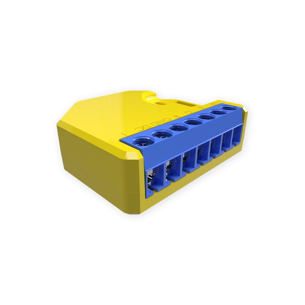
An ESP8266 with 2MB flash LED Controller.
- Supports any 12v or 24v White, RGB, or RGBW led strips and 12/24v led bulbs, with up to 288W combined power
- Supports four-way PWM, applied to control four colors LED(R/G/B/W) for colored lights, color temperature lights, and general lights
- A separate 12V/24V power supply unit is required
- 12V --> 144W combined / 45W per Channel
- 24V --> 288W combined / 90W per Channel
- Shelly RGBW2 Knowledge Base
- Shelly RGW2 API Reference
⚠️️Special Shelly Attention⚠️️~
DO NOT CONNECT ANYTHING TO ANY GPIOs OF THESE DEVICES!
No sensors, no switches, nothing!
There is no galvanic isolation between the DC Inputs and the GPIOs.
Do not connect AC/DC power and the serial connection at the same time!
Only use a Shelly as designed.
Serial Connection~
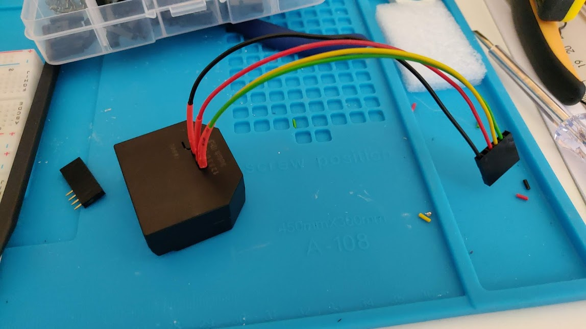
The Shelly RGBW2 model comes with a partially exposed programming/debug header which can be used to flash Tasmota on the device. A USB-to-UART adapter is needed as well as a reliable 3.3V with at least 350 mA drive capability. The following diagram shows the device pinout.

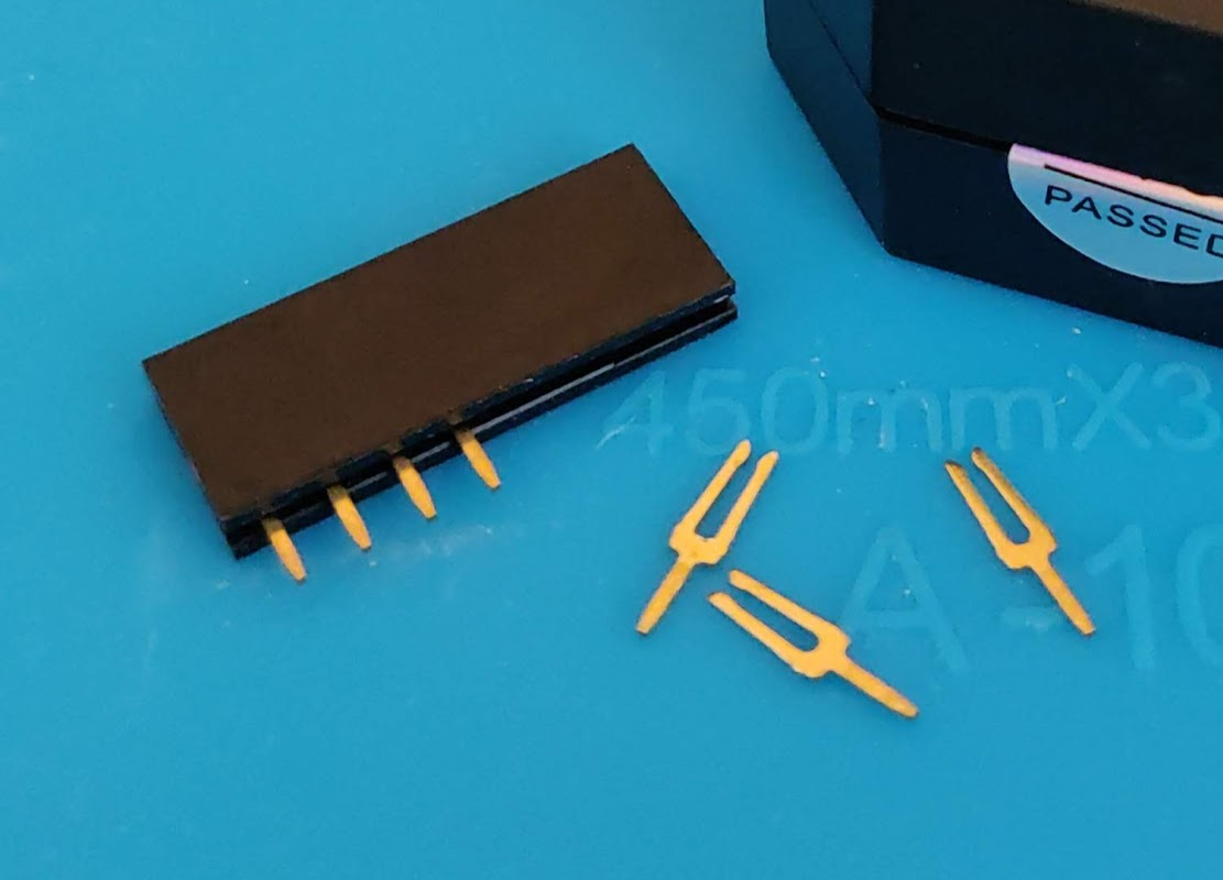
The onboard connector is 1.27mm pitch with 1mm diameter holes. Normal Dupont cables won't fit. To avoid damaging the PCB, use either a stripped Ethernet cable and breadboard as an adapter, or female header socket legs (see image below). The legs of a female header socket fit nicely. Solder them to custom-crimped Dupont wires for use with your USB-to-UART adapter. These often come with Wemos D1 Mini boards in multiple lengths.
Template~
| GPIO | Component |
|---|---|
| 0 | None |
| 1 | None |
| 2 | LEDLink |
| 3 | None |
| 4 | PWM4 |
| 5 | USER |
| 9 | None |
| 10 | None |
| 12 | PWM1 |
| 13 | Button1 |
| 14 | PWM3 |
| 15 | PWM2 |
| 16 | None |
| 17 | OpAmp Current Monitor |
{"NAME":"ShellyRGBW2","GPIO":[0,0,157,0,40,89,0,0,37,17,39,38,0],"FLAG":7,"BASE":18}
Energy metering is done by a LM321 OpAmp (1mOhm Shunt low side) via GPIO17.
If you want to use a push button, you should take a look at the Button and Switches.
If you want the buttons to respond instantly, go to the console and type SetOption13 1.
If you want press/double press/hold functionality, run instead Backlog SetOption1 1; SetOption11 1; SetOption32 20 to enable all three states and set hold time of 2 seconds. Use SetOption32 to set another hold time.
Flash mode~
To be able to flash the Tasmota firmware you need to get into flash mode. Connect a wire from GPIO0 to ground when powering on the device. For further information have a look at programming mode.
Calibration~
After successfully flashing Tasmota and selecting the template for the Shelly RGBW2, you can start configuring the power consumption.
-
Disconnect the GPIOs and connect the Shelly RGBW to its future power supply. Set GPIO17 to ADC Input in the template configuration and click Save.
-
After restarting, the actual ADC value of the analog input is displayed on the Main Menu as Analog0. There should be no LED lights on at this time.
Make a note of this value. It's the baseValue passed to the
AdcParamcommand later on. -
In the template configuration, set GPIO17 to ADC CT Power and click Save.
-
Use the AdcParam command in the web console:
AdcParam 7, baseValue, Multiplier, Voltage/1000For a 12VDC power supply and a baseValue of 407, the command looks like this:
AdcParam 7, 407, 3282, 0.012 -
If there are no lights on, the Main Menu should show only the Voltage but no consumption.
- Connect a light source with a current consumption known to you. Or measure the current with a multimeter. Compare the displayed values in the menu and those of your meter. Please note that the measurement of the Shelly RGBW2 is very inaccurate due to its electrical construction.
Calculate the Analog CT Multiplier (optional)~
It may be necessary to calculate the Analog CT Multiplier value. Generally 3282 is sufficient.
- Set GPIO17 input back to ADC Input.
- Note the baseValue when the light is switched off.
- Switch on the light and note the displayed analog value (comparisonValue) and the current value displayed by your meter (realValue).
-
Calculate the Multiplier value:
(comparisonValue - baseValue) x 100 / realValue = Multiplier
Example:
comparisonValue = 455 baseValue = 407 realValue 1.5A (455-407)*100/1.5 = 3200 -
Set GPIO17 input back to ADC CT Power and start at step 4 of the Calibration procedure.
Using the Attached AC Switch Adapter~
As described in AC Frequency Detection Switch section, the adapter sends pulses (by shorting red wire to GND), when AC voltage is present between the two black wires.
Shelly RGBW2 has an onboard pull-up resistor to 3.3V. To make it work correctly, set GPIO5 to Switch_n mode. Then use the 'SwitchDebounce' command to set the number of pulses required for the switch to be recognized as on or off. For example, SwitchDebounce 69.
Use Rules to Control Both Switches~
If SetOption37 is set to 128 the RGB and White is split, use this rule to switch both RGB and White on/off with the connected hardware switch:
Rule1 ON Power1#State DO Power2 %value% ENDON
Rule1 1
Ghost switching~
The inputs on Shelly devices appear to be notoriously susceptible to interference. Therefore ghost switching can happen if the wires are long (>1m / 3ft). If you experience this issue, you might want to experiment with the switch debounce delay. It is set to 50 milliseconds by default.
Use command SwitchDebounce 100 to change it to a less sensitive value, which might work better. The value can be set up to 1000 milliseconds.
Some issues were reported for this topic - search query
Light setup~
To get the equivalent of what Shelly calls "White mode", run SetOption68 1.
To switch back to what Shelly calls "Color mode" (the default), run SetOption68 0.
See Lights for more details.
PCB images~

