Sonoff B1
Sonoff B1 R2 is the replacement for Sonoff B1 and can be programmed the same way as the B1. See here for more background information.
Serial Flashing~
Please see the Hardware Preparation page for general instructions.
As always, you need to access the serial interface. First pop up the top part of the bulb with controlled force. The PCB as shown in the image will become visible.

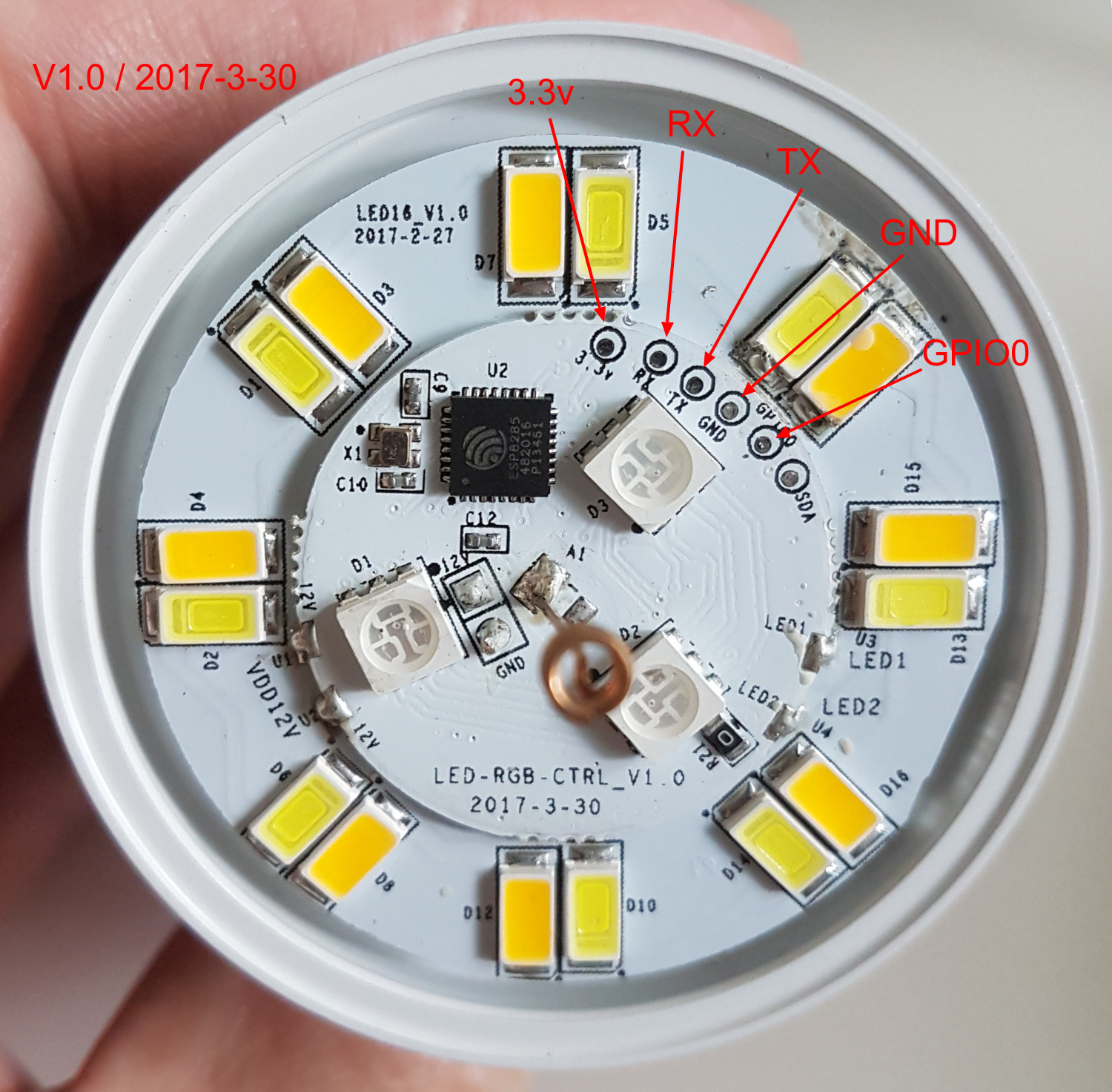
The four serial pins (3V3, RX, TX, GND) as well as the GPIO0 signal line are available as test points and clearly marked. Solder wires to those or use pogo pins as you prefer.
As with all modules pulling GPIO0 to GND is needed to put the chip in programming mode. You need to connect GPIO0 and GND during power up. An additional GND pad is available in the middle of the PCB.
NOTE: If experiencing trouble getting the B1 R2 into flash mode, try pulling GPIO to GND during power up and holding it for 20 to 25 seconds before release.
LED HEX10 Color Codes~
The Sonoff B1 uses a TEN charter HEX code for all colors. Colors tested with firmware 5.9.1 20171107: * 00000000A0 = WARM * 000000A000 = COOL * 0000A00000 = BLUE * FF14500000 = PURPLE * 551A8B0000 = DARK PURPLE * A300000000 = RED * 00ff000000 = GREEN
Official Sources~
- Itead Product Page: http://sonoff.itead.cc/en/products/residential/sonoff-b1
- Itead Shop: https://www.itead.cc/sonoff-b1.html
- Itead Wiki: (not available)