Sonoff Basic
Sonoff Basic - the one that started it all!
Serial Flashing~
Please see the Hardware Preparation page for general instructions.

You need to access the serial interface. The four serial pins (3V3, Rx, Tx, GND) are available in the middle of the PCB, right next to the on-board button. Newer versions of the Sonoff Basic device provide five pins below the button, ignore the pin furthest away from the Button (GPIO14 or I02) if available. The square pin right next to the button is the 3.3V line.
For flashing the Sonoff Basic, hold the button while connecting the 3.3V power. The LED remains off until the flashing process is done and the board is rebooted.
If your switch is powering up but is showing a solid-blink-reset pattern see this FAQ entry for advice.
- GPIO00 - BUTTON
- GPIO12 - RELAY
-
GPIO13 - LED1
-
GPIO03 - RX PIN
- GPIO01 - TX PIN
Sonoff Basic R3~
This is the board layout for the third design iteration of the Sonoff Basic. 
The Sonoff Basic R3 uses the ESP8285 chip. With this version, the mains power reverts to solder rails directly on the PCB. It also moves the Wi-Fi module to a separate PCB mounted on the main PCB. It makes access to the underside of the serial interface contacts quite difficult.
This version of the device supports the new Itead DIY architecture which allows OTA firmware upload. The device was reviewed by DigiblurDIY in this video.
The serial interface pins are broken out on the PCB making flashing using a serial adapter as well. Since the underside of the contacts is not easily reachable, use a solderless solution (i.e., friction) to maintain contact with the pins to flash the device.
Sonoff Basic R2~
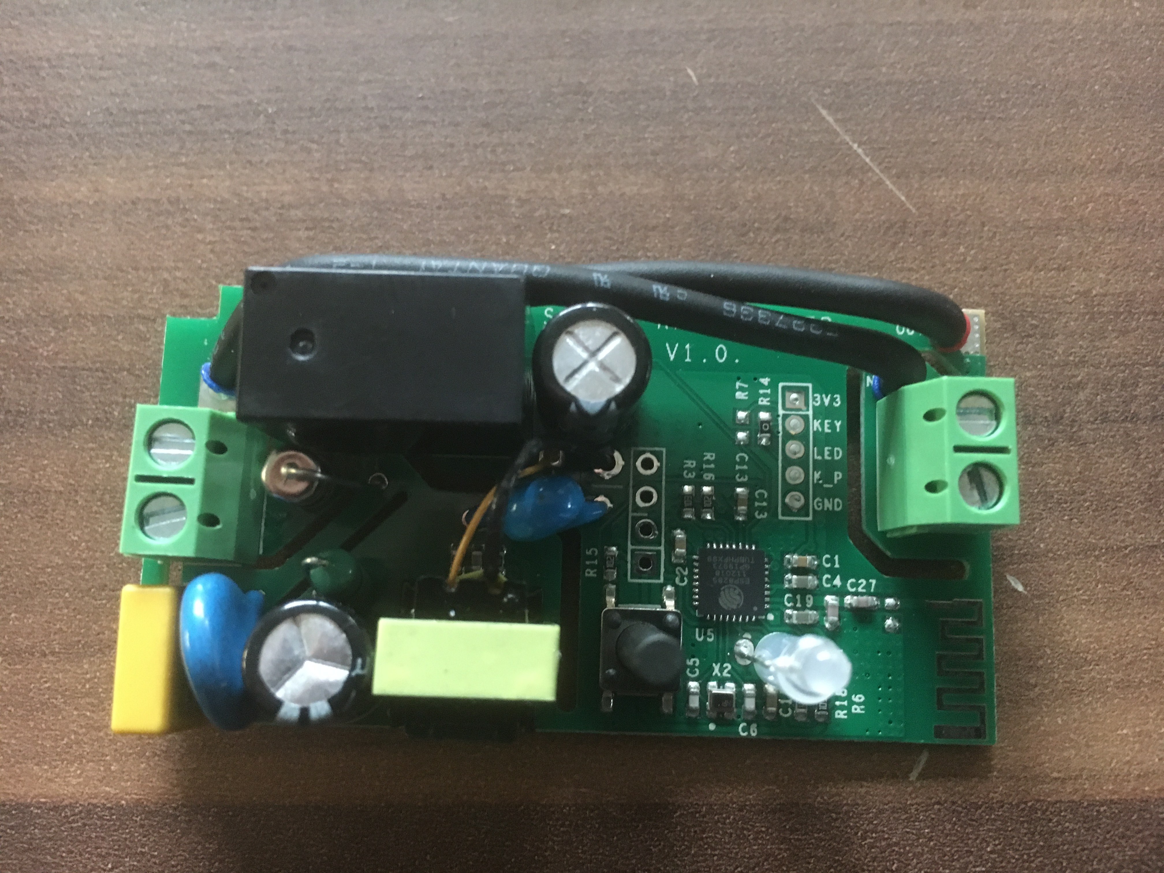
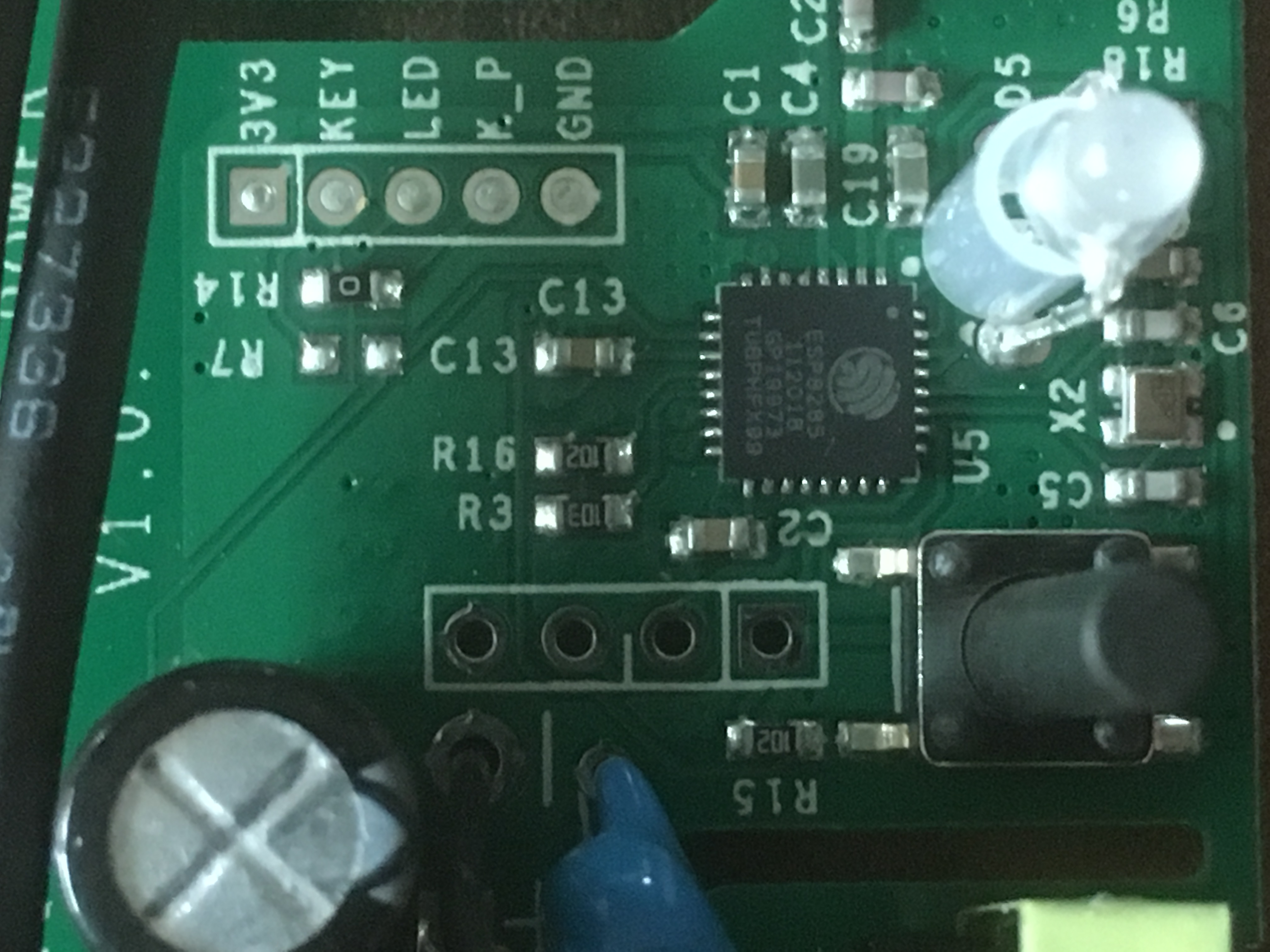
Around November 2018, Itead changed the layout of the Sonoff Basic (issue #4515). The new board is labeled as Sonoff RF R2 POWER V1.0. It is easily discerned from previous revisions since it uses wires instead of thick solder traces for mains power.
The new version of the Sonoff Basic smart switch uses an ESP8285 SoC with the 1MB flash integrated into the same SoC chip.
GPIO14 is no longer broken out to a contact on the PCB. Instead, GPIO02 (no pullup) is broken out. It is labeled as IO2 on the board. To use GPIO02, take care that it is not being pulled low when the device is booting. Otherwise, the device will not boot into its regular operational mode. Alternatively, you can use use GPIO03 (Rx) which does not have any boot function restrictions. However, both of these GPIO are pulled high momentarily after boot. This means that any connected device may "blink" when the Sonoff is powering up.
Unlike GPIO03, the GPIO02 PCB contact is not prepared for a pin. You will need to solder your cable directly on the board. Be careful. Too high a temperature or long heating can damage the contact and its connectivity. You should also make sure that there is no tension on the cable. Affix the cable with a cable tie and perhaps some hot glue.
GPIO02 as a user configurable input is implemented in the Sonoff Basic module (introduced in 6.3.0.15). If you use GPIO03, you must use a device template (rather than selecting the Sonoff Basic module), and also disable serial logging (
SerialLog 0).

You can remove the thick wires from the PCB to use the screw connection on the output side for low voltage. Then add a screw terminal next to the relay for the LINE OUT. This keeps all high voltage on one side of the board 
Sonoff Basic R1~
This is the board layout for the first board version of the Sonoff Basic.

(Image re-used from https://www.instructables.com/id/Use-Homie-Firmware-to-Drive-Sonoff-Switch-Module-E/ Thanks @amayii0)
Usable GPIO: - GPIO14 is broken out on the PCB adjacent to the GND pin. 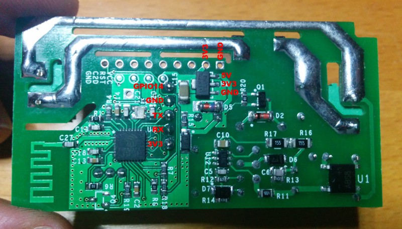 - GPIO13 - You must remove the bi-colour LED - GPIO04 - You must solder wire to pin on ESP chip