Sonoff Dual R2
Sonoff Dual R2 is the replacement for Sonoff Dual. Compared to the Dual the main differences/improvements for R2 are: * As the second microcontroller has been removed both relays are now controlled directly by an ESP8285 * The button is now directly connected to the ESP8285 * The header connector is now supported in Tasmota
Serial Flashing (Sonoff Dual R2)~
Please see the Hardware Preparation page for general instructions.
As always, you need to access the serial interface. VCC, RX, TX and GND are available at the bottom left end of the PCB in the image below. 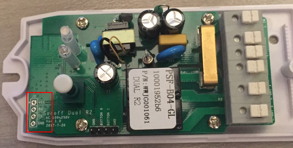
Programming the Sonoff Dual R2 is a breeze although the on-board-button is not connected to GPIO0. As with all ESP8266/ESP8285 modules pulling GPIO0 to GND is needed to put the chip in programming mode. You need to connect GPIO0 and GND during power up.
Luckily both GND and GPIO0 (as BUTTON 0) are available on the second header. A simple jumper between GND and BUTTON 0 while powering on will do.
For a video on how to flash the Sonoff Dual R2 with Tasmota, take a look here.
Use external switches~
The relays can be controlled by external push buttons or switches connected to the header at the designated positions. BUTTON 0 (on GPIO0) connected to GND controls Relay1 and BUTTON 1 (on GPIO9) connected to GND controls Relay2.
See the image on the right how to configure this functionality in Tasmota as Switch1 and Switch2.
NOTE Make sure not to use a switch that keeps the connection between GND and BUTTON 0 active while power is re-applied as the device will start in programming mode.
Note 2: GPIO9 and 10 can be safely used with an external switch (even rebooting with the contacts closed), and configured as such using a template. GPIO9 is available in the header, and GPIO10 is the board's button (you only need to solder a wire to the GPIO10 side of the button, no need to remove it).
Sonoff Dual (not R2)~
Serial Connection~
Please see the Hardware Preparation page for general instructions.
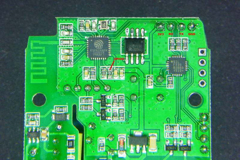
As always, you need to access the serial interface. The four serial pins (3V3, Rx, Tx, GND) are available at the short end of the PCB and can be seen on the left side of the first image and are labeled in red on the second image. For the v2.0 version of the board you need to cross-over the serial interface, see troubleshooting.
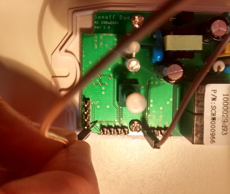
Programming the Sonoff Dual is more difficult because the on-board-button is not connected to GPIO0. As with all ESP8266 modules pulling GPIO0 to GND is needed to put the chip in programming mode. You need to connect GPIO0 and GND during power up.
GND can be found on all three headers. GPIO0 can be accessed two ways: 1. Unscrew the Sonoff Dual from the housing and access the underside of the PCB You can find GPIO0 on one side of a resistor as shown in the second image. 2. GPIO0 can be found on the small inter layer via pointed at in the first image. Attention: If the via is covered by silk screen (green) you need to expose the underlying conductive (copper) by careful scratching it off.
Restricted Button Functionality~
Please be aware, that the button on the Sonoff Dual will initially not have any functionality!
Other than on most Sonoff module the button is not connected to the normal button pin (GPIO0). After freshly flashing Tasmota (with the default module setting "Sonoff Basic"), the button will not act as described in the Buttons and Switches article. You will not be able to switch power or activate the special WiFi modes.
You will need to configure wifi credentials connecting directly to the wifi AP your Dual will broadcast or configure the module firmware config beforehand via user_config_override.h.
After configuring the device as a "Sonoff Dual", the button will regain normal functionality.
GPIO Locations~
GPIO4 => red, GPIO14 => orange 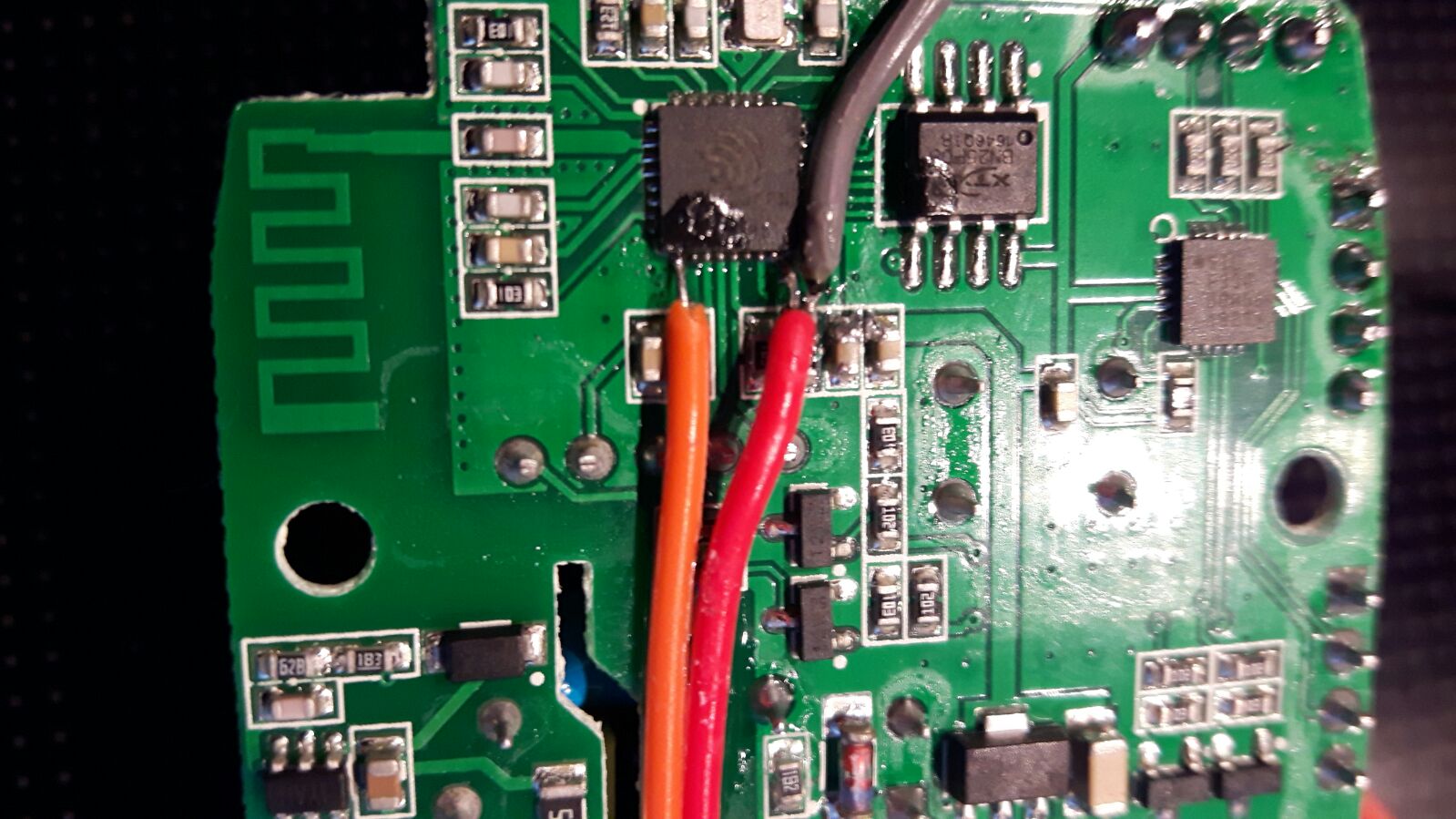
Solving intermittent relay switch errors~
Where most Sonoff's use GPIO to control one or more relays the Sonoff Dual and 4 Channel Inching Relay Assy do use the standard SERIAL interface to control the relays.
Commands are send from the ESP8266 via a 19200 baud serial connection to a dedicated chip that controls the relays.
It is therefore important to disable any serial communication to and from the device once you have debugged any anomalies.
To assist easy installation serial logging is enabled by default in user_config_override.h for all Sonoffs. Once in production it's wise to turn it off for all Sonoffs. For the Dual it is almost mandatory to turn it off.
Execute command seriallog 0 once to turn all communication on the serial port off.
If within 10 minutes no input is received serial communication is turned off too.
Another reason for intermittent switching errors can be Power Saving. Make sure it is disabled by executing the command sleep 0.
Official Sources~
- Itead Product Page: http://sonoff.itead.cc/en/products/sonoff/sonoff-dual
- Itead Shop: https://www.itead.cc/sonoff-dual.html
- Itead Wiki: https://www.itead.cc/wiki/Sonoff_Dual