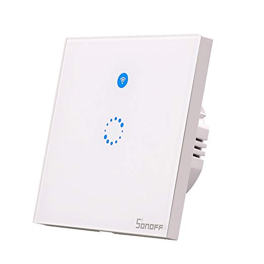
Sonoff-T1 seems to be an evolution of Sonoff Touch and exists in one, two or three button variations and contains a 433MHz receiver.
Based on the ESP8285, but using a Silabs EFM8BB1 microcontroller to extend the number of IOs needed to control 3 buttons, with separate relays and LEDs together with the radio. SYN470R is used as 433Mhz Radio. The chip for touch is unlabeled.
Read before flashing~
Tasmota has functionality to perform special actions on multiple button presses and long press for 40 seconds resets firmware to default. This will cause the T1 board to reset if relay board is not connected, because long press on Button1 will be detected. To avoid this, use command SetOption13 1 immediately after flashing Tasmota.
When powered solely with 3.3v from the serial-to-USB adapter long press will be detected by Tasmota on Button1.
When powered solely with 3.3v from the serial-to-USB adapter RF functions do not work.
If you can't flash successfully lower the baud rate, most likely to 74880.
Serial Flashing~
Sonoff T1 UK~
The front circuit board should be disconnected from the rear relay board to prevent power draw upsetting the flashing process. The unit must be powered up before attempting to enter programming mode. If touch Button1 is held while power is connected, the device will not go enter flash mode. The touch IC does not have time to recognise the key-press before the device boots.
Touch Board VER:1~
The following board layouts are from the 3 variants of the Sonoff T1 UK variant and are marked Sonoff T1 R2 UK Touch Board, Ver 1.0.


- Entering Flashing mode varies between the 1, 2 and 3 channel versions. See the above picture for button nomenclature used. (The variations between the 3 versions appear to be managed by the touch IC rather than in the ESP).
To enter flashing mode the unit should be powered and connected to the programmer of choice. Touch Button 1 should then be held while the reset button (4) is pressed. When the device reboots, Button 1 can be released. OR - Double-press the reset-button
Try option 1 OR option 2. This will cause the unit to reboot into flash mode. This is confirmed on a serial console (74880 baud) by the boot mode displaying (1,x) indicating that we are booted to the bootloader and not the flash. You can also confirm booted to flash without a serial console, the main led should be off and the backlight LEDs lit dimly. There is no longer a need to solder anything to GPIO0 or to ground it while powering up for Ver1.0; this step is replaced by the above button sequence. However, GPIO0 to GND is the only way for Ver1.1 boards.
Touch Board Ver:1.1~
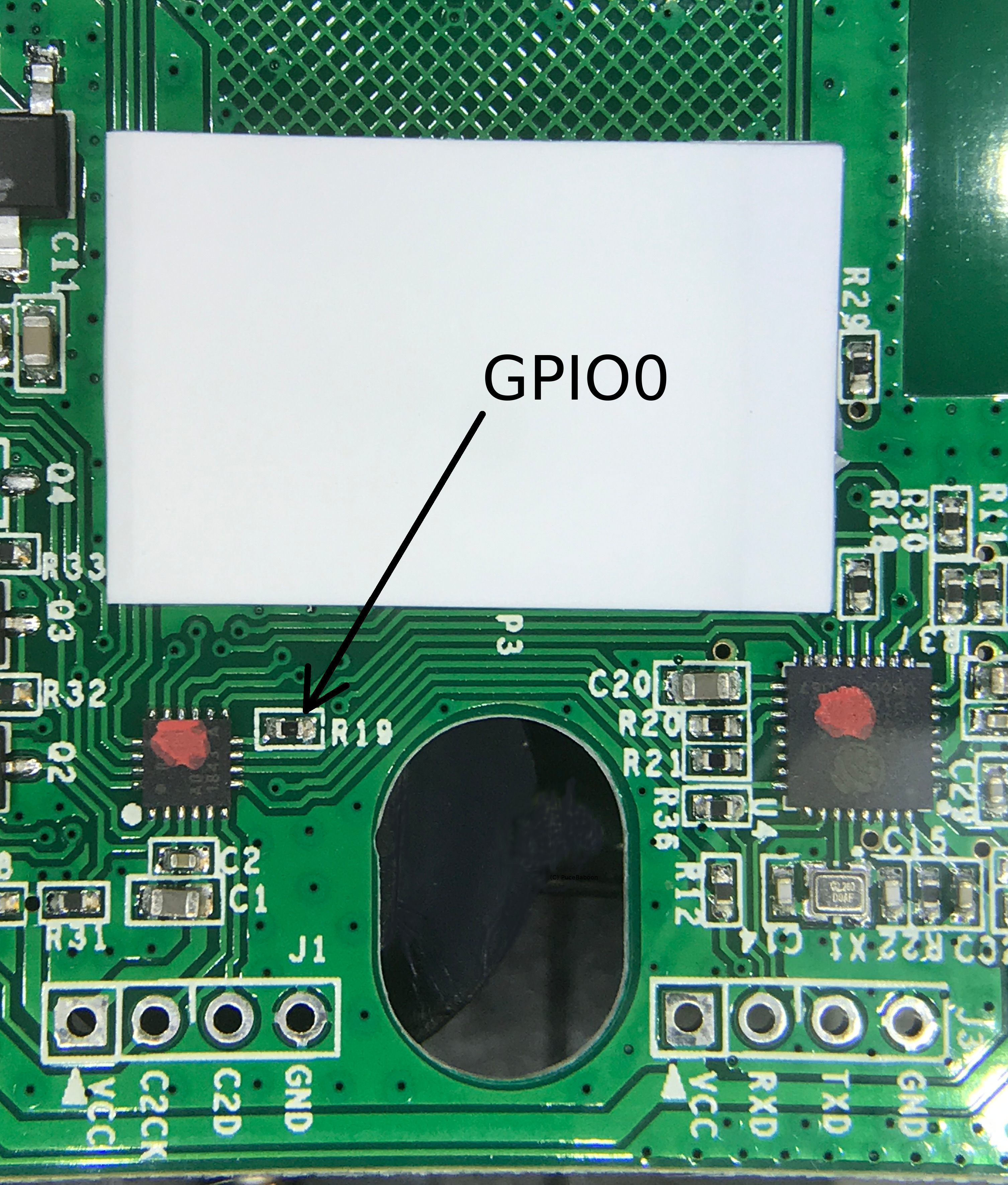
 Notes: 1. There is not enough room with this version to solder header pins to the programming port and still close the case. One possibility is to slightly bend the pins of a 4-way header and push it into the holes, removing it after programming. 2. GPIO0 is connected to the helper chip on this version, so the only way to get Ver1.1 of the board into flash mode is to solder a lead onto the resistor R19 from pin 15 on the ESP chip (GPIO0) and connect this lead to GND on power up; the device will set all the touch pads to dim and the WiFi LED D3 will NOT be on at all. 3. The connection marked 'LOG' on the J3 header is GPIO2.
Touch Board Ver:2.0~
The 3v3, GND, TX, RX are pretty well labeled, but for BOOT mode you need to connect "TP1 KEY0" to the ground. See more details
WARNING!! Do not attempt to power the device from your serial-to-USB adapter when connected to the relay board. This draws too much power and will cause the ESP to reboot frequently and reset all the configured settings.
Sonoff T1 EU~
For most devices, the UK version flashing guide may work.
Sonoff T1 EU 1CH (2018-06-04)~
 All the flashing pins are in the front top right corner (sorry about covering them with the wires). From top to bottom: - LOG (GPIO2 not used) - GND - TXD - RXD - VCC
To flash simply connect GND, TXD, RXD, and VCC as any regular ESP. Hold the touch button, press reset at once, then it boots into flash mode (no blinking WiFi LED, dimmed touch button). If this does not work, try shorting R19 to GND as shown in "Touch Board VER:1.1" * Stock baud rate: 74880 * Relay pin: 0
Sonoff T1 EU 2CH (v1.0)~
For 2 Channel board version 1.0, you need to solder (or otherwise permanently connect) GPIO0 (R19) to GND before powering the board and only disconnect them once the flashing is complete.

After having connected GPIO0 and GND, power the board - it will boot directly to flashing mode. Flash your firmware and disconnect the board.
Sonoff T1 EU 1CH/2CH/3CH (2018-10-03)~

There are two pin headers (J1 and J3) and no reset button. J3 is used for flashing. GPIO0 is exposed on the back as test point (TP2/GPIO0). Connecting it to any ground such as the ground from J1 when powering up puts the ESP8255 into flash mode. Baud rate for flashing is 74880.
Sonoff T1 US~
It appears that SonOTA may work again with Sonoff firmware v2.0.1 or greater. This needs to be verified for this specific device. To get it working you can simply plug it to mains, once it's powered up, press and hold the button that's closer to the Wi-Fi logo (you'll hear a beep sound). Keep holding it until you hear that beep for the second time. Now let go. The Wi-Fi light should blink in pairs of 3. Now repeat the procedure (Press and hold until you hear the beep 2 times). Now you should be seeing the Wi-Fi logo flashing rapidly. You can proceed to try and flash with SonOTA now.
US Model of 3-button T1, received direct from Sonoff China 2018-05-12~
Front photo (Google photos) Rear photo (Google photos) (Sorry about the tape smudges).
The header labels on J3 are accurate (apparently some boards have TX and RX reversed; this doesn't seem to suffer that).
Flashed with SonOTA. Above method of getting into flash mode doesn't seem to work.
UPDATE: I did flash it with the FTDI method. To put then in flash mode press 2 times quickly the internal switch S1.
UPDATE 2: Confirmed by another user that flashed with SonOTA works as described on "Preparing"
Sonoff T1 US 3 Gang~
The jump-wire method to enter the flash mode: * Jump the wire as attached picture * While keeping the wire connected then plug the serial-to-USB adapter to the computer * Wait for 1 to 2 seconds then release the jump-wire * You can start flashing the Sonoff T1 US 3C. 
Sonoff TX US 2/3 Gang~
The PCB layout for the TX/T0 model (vertical, black or white face-plate with squared-off, LED-lit buttons) is different again from the original T1. There is no TP2/GPIO0 test point on the back of the PCB and R19 has moved. The basic instructions for flashing the T1 (with a USB adapter) still work.
~
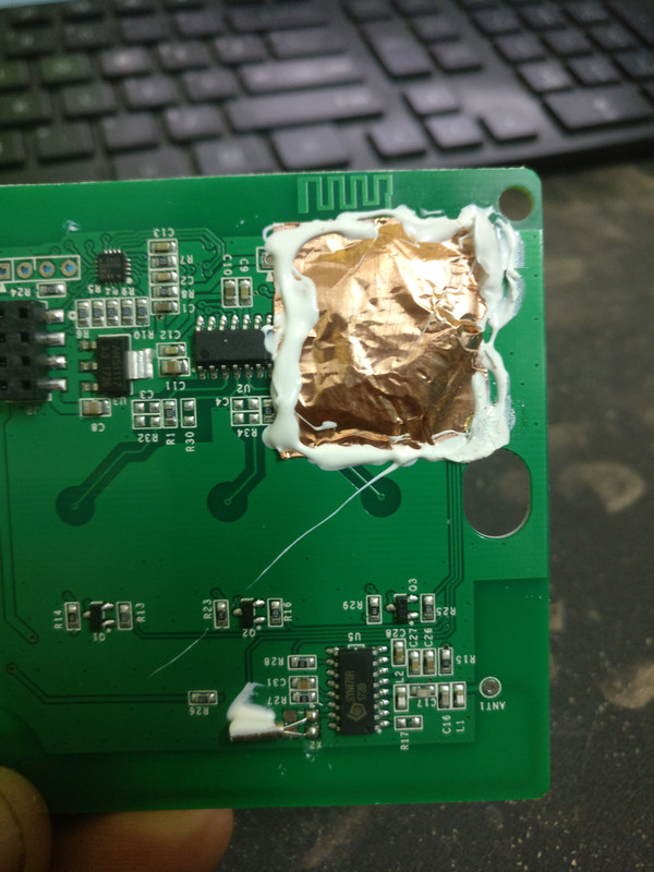
It seems that Sonoff is trying to seal off the ESP using some glue see image:
433MHz remote~
The Tasmota firmware is compatible with the RF remote feature built in to the T1 modules. Pairing a new remote is the same procedure as a stock Sonoff, i.e., hold the desired button on your sonoff until you are given 1 beep (approx 7 seconds), press the button on your RF remote. The Sonoff will beep to confirm the pairing. To unpair a remote, press until you are given 2 beeps, press the button on your RF remote. The Sonoff will beep to confirm the unpairing.
Circuit~
ESP8285
GPIO0 EFM8BB1 P1,3 Switch 1 input (Goes low when first touch button is pressed)
GPIO04 is connected to the small (soft) reset button on the front.
GPIO09 EFM8BB1 P1,4 - Switch 3 input (Goes low when third touch button is pressed)
GPIO10 EFM8BB1 P1,5 - Switch 2 input
GPIO13 is connected to status LED D3.
GPIO12 Relay 1
GPIO5 Relay 2
GPIO4 Relay 3
GPIO2 is connected on J3 pin 5 (LOG)
On the EFM8BB1 (QFN20 package)
P0,0 Relay 1
P0,1 Relay 2
P0,2 Relay 3
P0,3 Button 1
P0,4 Button 2
P0,5 Button 3
P0,6 SYN470R Data Out
P0,7 Buzzer
P1,0 Led button 1
P1,1 Led button 2
P1,2 Led button 3
P1,3 ESP8285 GPIO0
P1,4 ESP8285 GPIO09
P1,5 ESP8285 GPIO10
P1,6 ESP8285 EXT_RSTB (RESET)
Ghost Switching~
Some of these devices are prone to hardware ghost switching. You may need to experiment with ButtonDebounce and SetOption40 to reduce or eliminate these issues.
Also, during the flashing process, you may have soldered a lead to GPIO0 in order to connect it to GND for putting the ESP into programming mode. If there are any random oscillations on GPIO0, this can trigger the relay. The contacts on the PCB are very close together. Check that you don't have any stray solder to another contact. Even if there isn't contact, over time heat and humidity can cause any residual flux to become resistive and allow conductivity. Be sure to clean everything after removing any leads.
Known so far~
- When pushing a button, the touch chip lift the power high to the EFM8BB1, and the EFM8BB1 chip ties the signal line for each button low, for the full duration of the keypress. Debouncing is not needed.
- 433MHz remotes are compatible with the Tasmota firmware
- DO NOT attempt to power the device from your programmer when connected to the relay board. This draws too much power and will cause the ESP to reboot frequently and will reset all the configured settings.
- The relays state can be set on the GPIO's 12, 5 and 4.
- The switch status can be read on GPIO's 0, 10 and 9. Push button active low.
Unknown so far~
- Where GPIO15 is connected? Over R18 10kOhm pull-down only?
Official Sources~
Sonoff T1 UK~
The Sonoff T1 UK with 1 to 3 gang is fully supported by Tasmota starting with version 5.6.1.
Sonoff T1 EU~
The Sonoff T1 EU with 1 to 3 gang is fully supported by Tasmota starting with version 5.6.1.
Sonoff T1 US~
The Sonoff T1 US with 1 to 3 gang was launched March 2018.