Sonoff Touch
- Itead Product Page
- Itead Shop
- Itead Wiki: (n/a)
Unlike most Sonoff modules, the Sonoff Touch is based on the ESP8285 rather than the ESP8266. The actual chip inside may be a PSF-A85.
Serial Connection~
Please see the Hardware Preparation page for general instructions.
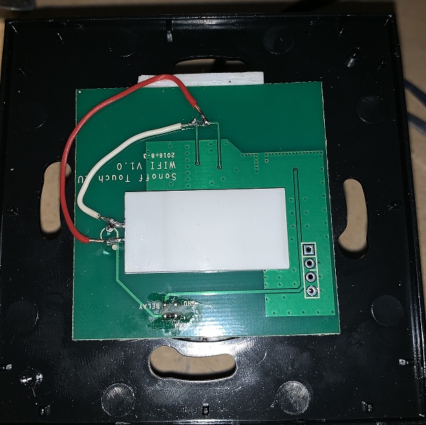
As always, you need to access the serial interface. Carefully remove the top PCB from the assembly. The hidden underside of the PCB contains the ESP8285 as shown in the pictures. The four serial pins (3V3, Rx, Tx, GND) can be seen in the pictures for the US version (left) and the EU version (right) of the module PCB.


Be careful while removing and reassembling the top PCB. The touch sensor should be back in its intended place. Be sure to not touch it directly during the modifications.
The Sonoff Touch button is not connected to GPIO0 and hence cannot be used to bring the module into Programming Mode. A connection between GPIO0 and GND needs to be made manually. GPIO0 can be found on the right side of the ESP8285 and is the second pin from the bottom, as can be seen on the pictures.
Note: Even if you have the PSF-A85 chip inside instead of a default ESP8285, the GPIO0 pin is in the same location. Pay attention to the corner of the chip with three unused solder contacts. That is where the external antenna connector is located in the images above. The PSF-A85 in the Sonoff Touch does not have the external antenna connector soldered on.
Control ON/OFF Leds on Sonoff Touch solution~
Solder the switch LED where the Wi-Fi LED is and then you can control the LED by using the command LedPower ON. The Switch LED is on all the time, even when the switch is off so you can easily find the switch in the dark.
Alternatively, you can solder the switch LED on 3.3v and ground but then you can't control the LED, it is always on and very bright.

