TYWE3S
Pinout for flashing TYWE3S devices. Module has a nearly identical pinout to ESP-12 module series.
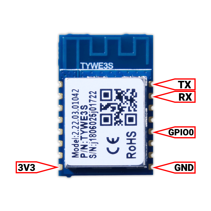
TYWE3S Wiring for Flashing~
| TYWE3S | Serial Programmer |
|---|---|
| Vcc | 3.3V |
| EN | 3.3V |
| TX | RX |
| RX | TX |
| GND | GND |
| GPIO0 | GND |
Make sure to ground GPIO0 during boot.
Additional Information~
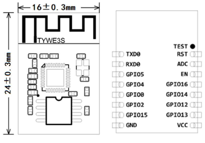
| Pin Number | Symbol | IO type | Function |
|---|---|---|---|
| 1 | TXD0 | O | UART0_TXD |
| 2 | RXD0 | I/O | UART0_RXD |
| 3 | GPIO5 | I/O | GPIO5_05 |
| 4 | GPIO4 | I/O | GPIO5_04 |
| 5 | GPIO0 | I/O | GPIO5_0 (Participate in the module power-on initialization process,use with caution) |
| 6 | GPIO2 | O | UART0_TXD (Used to print module internal information) |
| 7 | GPIO15 | O | GPIO_15 (Participate in the module power-on initialization process,use with caution) |
| 8 | GND | P | Power Reference Ground |
| 9 | VCC | P | Module Power Pin (3.3V) |
| 10 | GPIO13 | I/O | GPIO_13 |
| 11 | GPIO12 | I/O | GPIO_12 |
| 12 | GPIO14 | I/O | GPIO_14 |
| 13 | GPIO16 | I/O | GPIO_16 (Use 10K pull-up resistor for use) |
| 14 | EN | I | Module enable pin,normal use needs to receive 3.3V |
| 15 | ADC | AI | ADC port, 10-bit precision SAR ADC |
| 16 | RST | I/O | Hardware reset pin (low level effective, internal pull-up resistance) |
For Switches and dimmers with additional MCU check guide here